Page 12 | BRADFORD WHITE CORP. |
|
|
|
|
2.3.3 Vertical Vent Terminal
When the unit is vented through the roof, the vent must extend at least 3 feet (0.9m) above the point at which it penetrates the roof. It must extend at least 2 feet (0.6m) higher than any portion of a building within a horizontal distance of 10 feet (3.0m), and high enough above the roof line to prevent blockage from snow. When the combustion air is taken from the roof, the combustion air must terminate at least 12" (30cm) below the vent terminal (see Figure 2).
2.3.4Vertical Combustion Air Terminal
When combustion air is taken from the roof, a
2.4Common Vent Test — Boilers
When an existing boiler is removed from a
common venting system, the common venting system is likely to be too large for proper venting of the appliances remaining connected to it.
At the time of removal of an existing boiler, the following steps shall be followed with each appliance remaining connected to the common venting system placed in operation, while the other appliances remaining connected to the common venting system are not in operation.
1.Seal any unused openings in the common venting system.
2.Visually inspect the venting system for proper size and horizontal pitch and determine there is no blockage or restriction, leakage, corrosion and other deficiencies which could cause an unsafe condition.
3.Insofar as it is practical, close all building doors and windows and all doors between the space in which the appliances remaining connected to the common venting system are located and other spaces of the building. Turn on clothes dryers and any appliance not connected to the common venting system. Turn on any exhaust fans, such as range hoods and bathroom exhausts, so they will operate at maximum speed. Do not operate a summer exhaust fan. Close fireplace dampers.
4.Place in operation the appliance being inspected. Follow the lighting instructions.
Adjust thermostat so appliance will operate continuously.
5.Test for spillage at the draft hood relief opening after 5 minutes of main burner operation. Use the flame of a match or candle, or smoke from a
cigarette, cigar or pipe.
6.After it has been determined that each appliance remaining connected to the common venting system properly vents when tested as outlined above, return doors, windows, exhaust fans, fireplace dampers and any other gas burning appliance to their previous conditions of use.
7.Any improper operation of the common venting system should be corrected so that the installation conforms to the National Fuel Gas Code, ANSI Z223.1/NFPA 54 and/or CSA B149.1, Installation Codes. When resizing any portion of the common venting system, the common venting system should be resized to approach the minimum size as determined using the appropriate tables in Part II of the National Fuel Gas Code, ANSI Z223.1/ NFPA 54 and/or CSA B149.1, Installation Codes.
2.5Vent Terminals for Outdoor Units
For outdoor applications, the vent and
combustion air openings must be covered with proper terminals to prevent rain, snow and other objects from falling into the Copper Brute II.
If local codes allow, outdoor installations may use 1' of appropriately sized galvanized single wall or
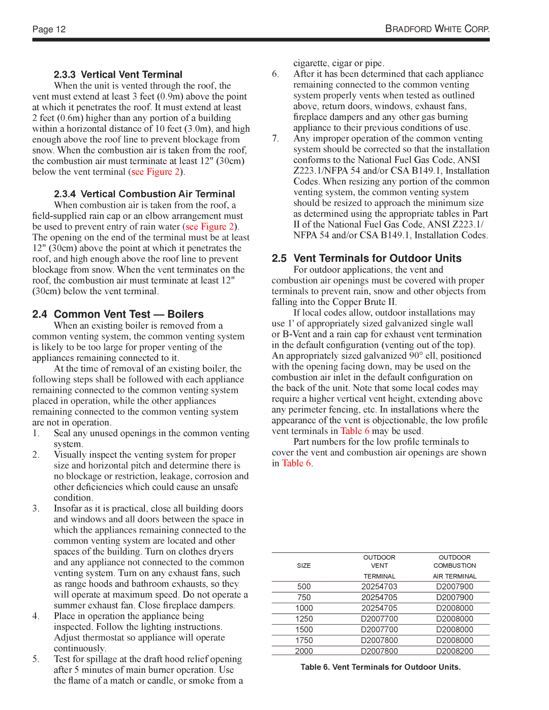
Part numbers for the low profile terminals to cover the vent and combustion air openings are shown in Table 6.
| OUTDOOR | OUTDOOR |
SIZE | VENT | COMBUSTION |
| TERMINAL | AIR TERMINAL |
500 | 20254703 | D2007900 |
750 | 20254705 | D2007900 |
1000 | 20254705 | D2008000 |
1250 | D2007700 | D2008000 |
1500 | D2007700 | D2008000 |
1750 | D2007800 | D2008000 |
2000 | D2007800 | D2008200 |
Table 6. Vent Terminals for Outdoor Units.