COPPER BRUTE II (500 - 2000) | Page 7 |
|
|
|
|
1.6 Locating
For best results, a
IIwater heater should be located within 15 feet (4.6m) of the storage tank(s). The pump is sized for 30 feet (9.1m) of piping.
If the appliance must be installed with longer piping runs, then larger diameter pipe or tubing shall be used. Consult the factory for assistance.
1.7 Locating
For the best results, a
If the appliance must be installed with longer piping runs, then larger diameter tubing shall be used. Consult the factory for assistance.
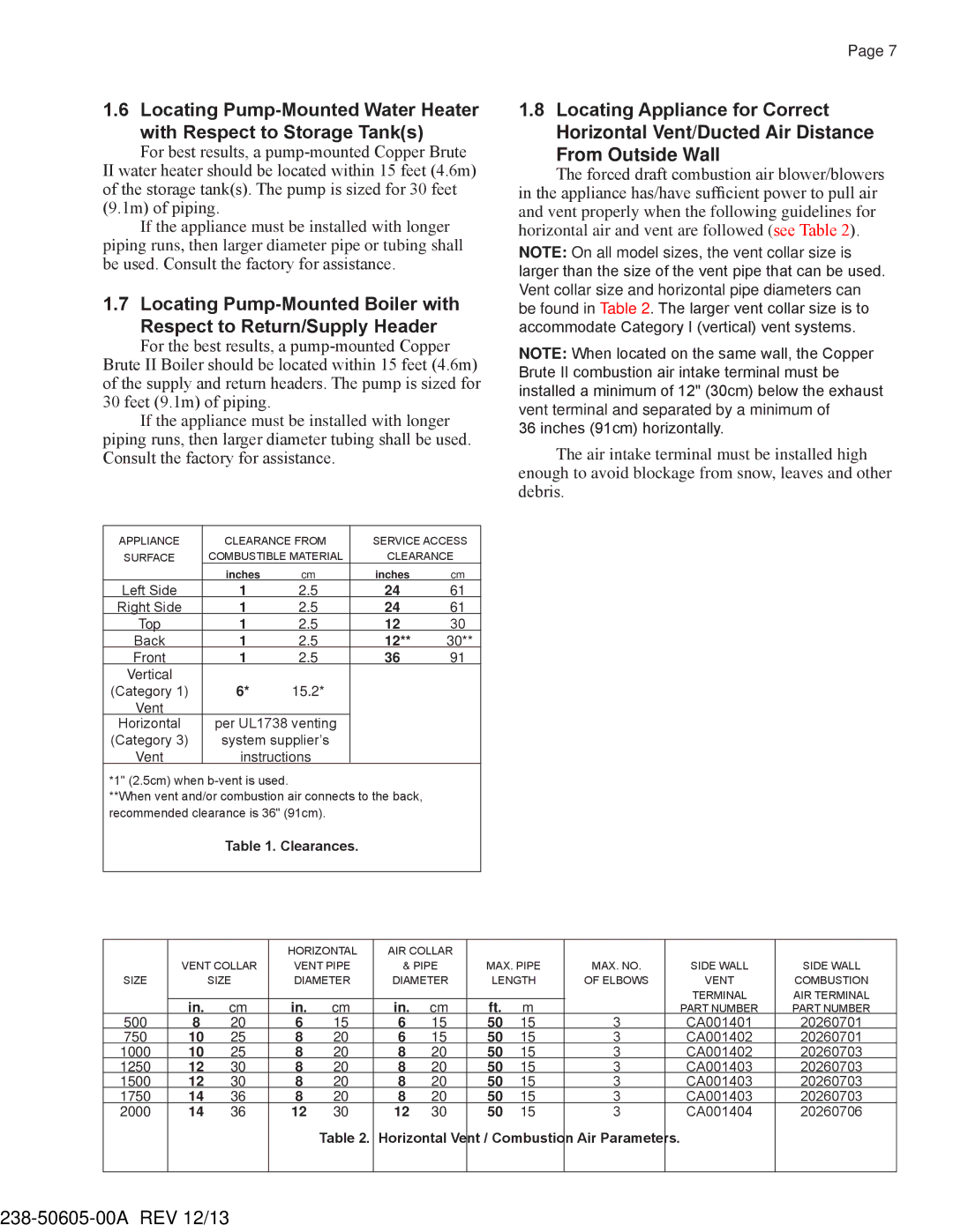
APPLIANCE | CLEARANCE FROM | SERVICE ACCESS | ||
SURFACE | COMBUSTIBLE MATERIAL | CLEARANCE | ||
| inches | cm | inches | cm |
Left Side | 1 | 2.5 | 24 | 61 |
Right Side | 1 | 2.5 | 24 | 61 |
Top | 1 | 2.5 | 12 | 30 |
Back | 1 | 2.5 | 12** | 30** |
Front | 1 | 2.5 | 36 | 91 |
Vertical | 6* |
|
|
|
(Category 1) | 15.2* |
|
| |
Vent |
|
|
|
|
Horizontal | per UL1738 venting |
|
| |
(Category 3) | system supplier’s |
|
| |
Vent | instructions |
|
| |
*1" (2.5cm) when
**When vent and/or combustion air connects to the back, recommended clearance is 36" (91cm).
Table 1. Clearances.
1.8Locating Appliance for Correct
Horizontal Vent/Ducted Air Distance
From Outside Wall
The forced draft combustion air blower/blowers in the appliance has/have sufficient power to pull air and vent properly when the following guidelines for horizontal air and vent are followed (see Table 2).
NOTE: On all model sizes, the vent collar size is larger than the size of the vent pipe that can be used. Vent collar size and horizontal pipe diameters can be found in Table 2. The larger vent collar size is to accommodate Category I (vertical) vent systems.
NOTE: When located on the same wall, the Copper Brute II combustion air intake terminal must be installed a minimum of 12" (30cm) below the exhaust vent terminal and separated by a minimum of
36 inches (91cm) horizontally.
The air intake terminal must be installed high enough to avoid blockage from snow, leaves and other debris.
|
|
| HORIZONTAL | AIR COLLAR |
|
|
|
|
|
| ||
| VENT COLLAR | VENT PIPE | & PIPE | MAX. PIPE |
| MAX. NO. | SIDE WALL | SIDE WALL | ||||
SIZE |
| SIZE | DIAMETER | DIAMETER | LENGTH |
| OF ELBOWS | VENT | COMBUSTION | |||
|
|
|
|
|
|
|
|
|
|
| TERMINAL | AIR TERMINAL |
| in. | cm | in. | cm | in. | cm | ft. | m |
|
| PART NUMBER | PART NUMBER |
500 | 8 | 20 | 6 | 15 | 6 | 15 | 50 | 15 |
| 3 | CA001401 | 20260701 |
750 | 10 | 25 | 8 | 20 | 6 | 15 | 50 | 15 |
| 3 | CA001402 | 20260701 |
1000 | 10 | 25 | 8 | 20 | 8 | 20 | 50 | 15 |
| 3 | CA001402 | 20260703 |
1250 | 12 | 30 | 8 | 20 | 8 | 20 | 50 | 15 |
| 3 | CA001403 | 20260703 |
1500 | 12 | 30 | 8 | 20 | 8 | 20 | 50 | 15 |
| 3 | CA001403 | 20260703 |
1750 | 14 | 36 | 8 | 20 | 8 | 20 | 50 | 15 |
| 3 | CA001403 | 20260703 |
2000 | 14 | 36 | 12 | 30 | 12 | 30 | 50 | 15 |
| 3 | CA001404 | 20260706 |
|
|
|
| Table 2. | Horizontal Vent / Combustion | Air Parameters. |
|
| ||||
|
|
|
|
|
|
|
|
|
|
|
|
|