2.4Sensors and Actuators
This equipment has five photosensors and two mechanical switches as described below.
Sensor name | Type | Located on |
Document front sensor | Photosensor | Control panel PCB ASSY |
Document rear sensor | Photosensor (PI2) | Main PCB |
|
|
|
Photosensor (PH1) | Sensor PCB | |
Paper ejection sensor | Photosensor (PH2) | Sensor PCB |
|
|
|
Ribbon sensor | Photosensor (PI1) | Main PCB |
|
|
|
Cover sensor | Mechanical switch (SW1) | Main PCB |
|
|
|
Hook switch sensor* | Mechanical switch (SW1) | Hook switch PCB |
|
|
|
•Document front sensor which detects the presence of documents.
•Document rear sensor which detects the leading and trailing edges of pages to tell the control circuitry when the leading edge of a new page has reached the starting position and when the scan for that page is over.
•
•Paper ejection sensor which detects whether a paper jam has occurred.
•Ribbon sensor which detects whether the ink ribbon is loaded.
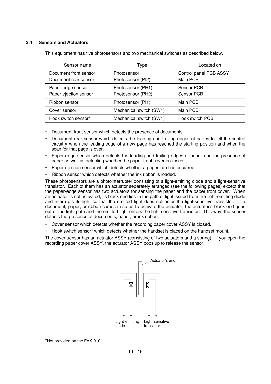
These photosensors are a photointerrupter consisting of a
•Cover sensor which detects whether the recording paper cover ASSY is closed.
•Hook switch sensor* which detects whether the handset is placed on the handset mount.
The cover sensor has an actuator ASSY (consisting of two actuators and a spring). If you open the recording paper cover ASSY, the actuator ASSY pops up to release the sensor.
*Not provided on the
