D e v i c e V i e w s
Physical Device View
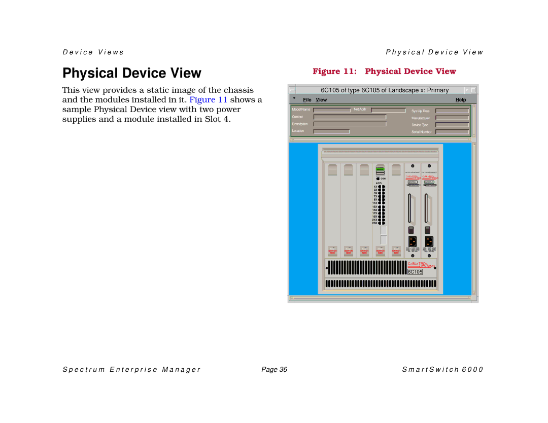
This view provides a static image of the chassis and the modules installed in it. Figure 11 shows a sample Physical Device view with two power supplies and a module installed in Slot 4.
P h y s i c a l D e v i c e V i e w
Figure 11: Physical Device View
6C105 of type 6C105 of Landscape x: Primary |
| * | File View |
|
|
|
| Help |
| |||
| Model Name |
|
| Net Addr |
|
| Sys Up Time |
|
| ||
|
|
|
|
|
|
| |||||
| Contact |
|
|
|
|
|
|
| Manufacturer |
|
|
|
|
|
|
|
|
|
|
|
| ||
|
|
|
|
|
|
|
|
|
|
| |
| Description |
|
|
|
|
| Device Type |
|
| ||
| Location |
|
|
|
|
| Serial Number |
|
| ||
|
|
|
|
|
|
| |||||
|
|
|
|
|
|
|
|
|
|
|
|
|
|
|
|
|
|
|
|
|
|
|
|
|
|
|
|
|
|
|
|
|
|
|
|
|
|
|
|
|
|
|
|
|
|
|
|
|
|
|
|
|
|
|
|
|
|
|
|
|
|
|
|
|
|
|
|
|
|
|
|
| Smart |
|
| Smart |
|
| Smart |
|
| SWITCH |
|
| SWITCH |
|
| SWITCH |
|
| 6000 |
|
| 6000 |
|
| 6000 |
|
|
|
|
|
|
|
|
|
|
ETHERNET |
COM |
CPU |
1X |
3X |
5X |
7X |
9X |
11X |
13X |
15X |
17X |
19X |
21X |
23X |
Smart
SWITCH
6000
Smart
SWITCH 6000
PDK 0 0 REDUNDANCY PDK 0 0 REDUNDANCY | ||||||||||||||
CaBLeTROn | CaBLeTROn | |||||||||||||
|
|
| SYSTeMS |
|
|
| SYSTeMS | |||||||
|
|
|
|
|
| |||||||||
|
|
|
|
|
|
|
|
|
|
|
|
|
| |
|
|
|
|
|
|
| ||||||||
|
|
|
|
|
|
| ||||||||
SNB0096520019 | SNB0096520019 | |||||||||||||
|
|
|
|
|
|
100 • 125 VAC | 100 • 125 VAC | ||||
200 • 250 VAC | 200 • 250 VAC | ||||
50 • 60 Hz | 50 • 60 Hz | ||||
CaBLeTROn
SYSTeMS
6C105
S p e c t r u m E n t e r p r i s e M a n a g e r | Page 36 | S m a r t S w i t c h 6 0 0 0 |
