I n t r o d u c t i o n
6C105 Chassis
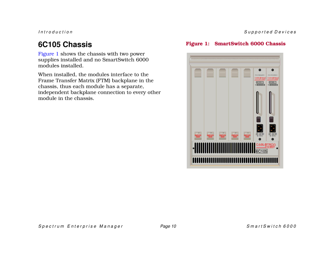
Figure 1 shows the chassis with two power supplies installed and no SmartSwitch 6000 modules installed.
When installed, the modules interface to the Frame Transfer Matrix (FTM) backplane in the chassis, thus each module has a separate, independent backplane connection to every other module in the chassis.
S u p p o r t e d D e v i c e s
Figure 1: SmartSwitch 6000 Chassis
PDK 0 0 REDUNDANCY | PDK 0 0 REDUNDANCY | |||||||||||||
CaBLeTROn CaBLeTROn | ||||||||||||||
|
|
| SYSTeMS |
|
|
| SYSTeMS | |||||||
|
|
|
|
|
|
|
|
|
|
|
|
|
| |
|
|
|
|
|
|
|
|
|
|
|
|
| ||
|
|
|
|
|
|
| ||||||||
SN |
|
|
| SN |
|
| ||||||||
B0096520019 | B0096520019 | |||||||||||||
Smart |
SWITCH |
6000 |
Smart |
SWITCH |
6000 |
Smart |
SWITCH |
6000 |
Smart |
SWITCH |
6000 |
Smart |
SWITCH |
6000 |
100 • 125 VAC | 100 • 125 VAC |
200 • 250 VAC | 200 • 250 VAC |
50 • 60 Hz | 50 • 60 Hz |
CaBLeTROn
SYSTeMS
6C105
S p e c t r u m E n t e r p r i s e M a n a g e r | Page 10 | S m a r t S w i t c h 6 0 0 0 |