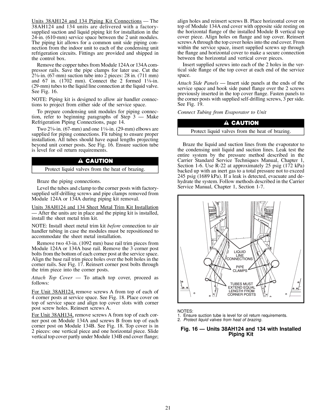
Units 38AH124 and 134 Piping Kit Connections Ð The 38AH124 and 134 units are delivered with a factory- supplied suction and liquid piping kit for installation in the 24-in. (610-mm) service space between the 2 unit modules. The piping kit allows for a common unit side piping con- nection from the indoor unit to each of the condensing unit refrigeration circuits. Fittings are provided and shipped in the control box.

Remove the copper tubes from Module 124A or 134A com- pressor rails. Save the pipe clamps for later use. Cut the 25¤8-in. (67-mm) suction tube into 2 pieces: 28 in. (711 mm) and 67 in. (1702 mm). Connect the 2 formed 11¤8-in. (29-mm) tubes to the liquid line connection at the liquid valve. See Fig. 16.

NOTE: Piping kit is designed to allow air handler connec- tions to project from either side of the service space.

To prepare condensing unit modules for piping connec- tion, refer to beginning paragraphs of Step 3 Ð Make Refrigeration Piping Connections, page 14.

Two 25¤8-in. (67-mm) and one 11¤8-in. (29-mm) elbows are supplied for piping connections. Fit tubing to ensure proper installation. All tubes should have equal lengths projecting beyond unit corner posts. See Fig. 16. Ensure suction tube is level for oil return requirements.

Protect liquid valves from the heat of brazing.

Braze the piping connections.

Level the tubes and clamp to the corner posts with factory- supplied self-drilling screws and pipe clamps removed from Module 124A or 134A during piping kit removal.

Units 38AH124 and 134 Sheet Metal Trim Kit Installation

ÐAfter the units are in place and the piping kit is installed, install the sheet metal trim kit.

NOTE: Install sheet metal trim kit before connection to air handler tubing in case the modules must be repositioned to accommodate the sheet metal installation.

Remove two 43-in. (1092 mm) base rail trim pieces from Module 124A or 134A base rail. Remove the 3 corner post bolts from the bottom of each corner post at the service space. Align the base rail trim piece holes over the bolt holes in the corner rails. See Fig. 17. Reinsert corner post bolts through the trim piece into the corner posts.

Attach Top Cover Ð To attach top cover, proceed as follows:

For Unit 38AH124, remove screws A from top of each of 4 corner posts at service space. See Fig. 18. Place cover on top of service space and align top cover slots with corner post screw holes. Reinsert screws A.

For Unit 38AH134, remove screws A from top of each cor- ner post on Module 134A and screws B from top of each corner post on Module 134B. See Fig. 18. Top cover is in 2 pieces: one vertical piece and one horizontal piece. Slide vertical top cover partly under Module 134B end cover flange;

align holes and reinsert screws B. Place horizontal cover on top of Module 134A end cover with opposite side resting on the horizontal ¯ange of the installed Module B vertical top cover piece. Align holes on ¯ange and top cover. Reinsert screws A through the top cover holes into the end cover. From within the service space, insert supplied screws up through the ¯ange and horizontal cover to make a secure connection between the horizontal and vertical cover pieces.

Insert supplied screws into each of the 2 holes in the ver- tical side ¯ange of the top cover at each end of the service space.

Attach Side Panels Ð Insert side panels at the ends of the service space and hook side panel ¯ange over the 2 screws previously inserted in the top cover ¯ange. Fasten panels to the corner posts with supplied self-drilling screws, 3 per side. See Fig. 19.

Connect Tubing from Evaporator to Unit

Protect liquid valves from the heat of brazing.

Braze the liquid and suction lines from the evaporator to the condensing unit liquid and suction lines. Leak test the entire system by the pressure method described in the Carrier Standard Service Techniques Manual, Chapter 1, Section 1-6. Use R-22 at approximately 25 psig (172 kPa) backed up with an inert gas to a total pressure not to exceed 245 psig (1689 kPa). If a leak is detected, evacuate and de- hydrate the system. Follow methods described in the Carrier Service Manual, Chapter 1, Section 1-7.

NOTES:

1.Ensure suction tube is level for oil return requirements.

2.Protect liquid valves from heat of brazing.

Fig. 16 Ð Units 38AH124 and 134 with Installed

Piping Kit

21

Page 21
Image 21
Carrier 38AH044-084 specifications Units 38AH124 and 134 with Installed Piping Kit

38AH044-084 specifications

The Carrier 38AH044-084 is an innovative air conditioning unit designed to provide efficient cooling solutions for residential and light commercial applications. This model is a part of Carrier's Aqua Series and is well-regarded for its combination of performance, energy efficiency, and innovative features.

One of the standout characteristics of the Carrier 38AH044-084 is its high-efficiency rating, which often exceeds the minimum efficiency standards set by the Department of Energy. Its Seasonal Energy Efficiency Ratio (SEER) rating is commendable, indicating significant energy savings over traditional air conditioning units. This efficiency translates to lower utility bills and a reduced carbon footprint, making it an environmentally friendly option.

In terms of technology, the Carrier 38AH044-084 is equipped with a modern scroll compressor. This type of compressor is known for its durability and quiet operation, contributing to a more pleasant indoor environment. The unit also incorporates advanced refrigerant technology, often using R-410A refrigerant, which is recognized for its lower environmental impact compared to older refrigerants like R-22.

The design of the 38AH044-084 focuses on ease of installation and maintenance. The compact footprint makes it suitable for various installation scenarios, whether on rooftops or ground levels. Additionally, the unit is engineered for durability, featuring weather-resistant components that can withstand harsh environmental conditions.

Another notable feature is the advanced airflow system, which ensures even distribution of cooled air throughout the space. This technology minimizes hot spots and enhances overall comfort. Furthermore, the unit supports a range of thermostatic controls, allowing users to customize their cooling experience according to their specific needs.

The Carrier 38AH044-084 is also designed with noise reduction in mind. Its sound-dampening technology helps minimize operational noise, making it a suitable choice for residential areas where noise levels are a concern.

In summary, the Carrier 38AH044-084 offers an excellent combination of energy efficiency, advanced technology, and user-friendly features. Whether for a home or a light commercial space, this unit provides reliable cooling performance while maintaining a focus on environmental responsibility and occupant comfort. With its robust design and innovative capabilities, it's a solid choice for those seeking effective and efficient air conditioning solutions.