SERVICE
ELECTRIC SHOCK HAZARD
Turn off all power to unit before servicing. The ON-OFF switch on control panel does not shut off control power; use ®eld disconnect.
Coil Cleaning Ð Clean the coils with a vacuum cleaner, compressed air, water, or a non-wire bristle brush.
Refrigerant Circuit
LEAK TESTING Ð Units are shipped with a holding charge of R-22 (see Table 3A, 3B, 4A, or 4B) and should be under sufficient pressure to conduct a leak test. If there is no pres- sure in the system, introduce enough nitrogen to search for the leak. Repair the leak using good refrigeration prac- tices. After leaks are repaired, system must be evacuated and dehydrated using methods described in GTAC II , Module 4, System Dehydration.
REFRIGERANT CHARGE (Refer to Table 3A, 3B, 4A, or 4B) Ð At the liquid line connection point on each circuit is a factory-installed liquid line service valve. On each valve is a 1¤4-in. Schrader connection for charging liquid refrigerant.
Charging with Unit Off and Evacuated Ð Close liquid line service valve before charging. Weigh in charge shown in Table 3A, 3B, 4A, or 4B. Open liquid line service valve; start unit and allow it to run several minutes fully loaded. Check for a clear sight glass. Be sure clear condition is liq- uid and not vapor. Complete charging the unit in accordance with Start-Up, Adjust Refrigerant Charge, page 39.
Charging with Unit Running Ð If charge is to be added while unit is operating, it is necessary to have all condenser fans and compressors operating. It may be necessary to block con- denser coils at low-ambient temperatures to raise condens- ing pressure to approximately 280 psig (1931 kPag) to turn all condenser fans on. Do not totally block a coil to do this. Partially block all coils in uniform pattern. Charge vapor into compressor low-side service port located above oil pump crankshaft housing. Charge each circuit until sight glass shows clear liquid.
Troubleshooting Ð Refer to Troubleshooting chart lo- cated at back of book.
Oil Pressure Safety Switch (OPS) Ð An oil pres- sure safety switch for each of the independent refrigerant circuits shuts off the compressor in that circuit if oil pressure is not established at start-up or maintained during operation. If the OPS stops the unit, determine and correct the cause before restarting the unit. Failure to do so constitutes equip- ment abuse and could affect the warranty.
Compressor Motor Protection
CIRCUIT BREAKER Ð A manual reset, calibrated trip cir- cuit breaker for each compressor protects against overcur- rent. Do not bypass connections or increase size of circuit breaker for any reason. If trouble occurs, determine the cause and correct it before resetting the breaker.
DISCHARGE GAS THERMOSTAT Ð A sensor in the cylinder head of each compressor (Fig. 29) shuts down the compressor if excessively high discharge gas temperature is sensed. If the discharge gas thermostat shuts the unit down, it may be reset by the thermostat or power disconnect switch.
CRANKCASE HEATER (See Fig. 29) Ð Each compressor has an electric crankcase heater located in the bottom cover.
The heater is held in place by a clip and bracket and must be tightly connected since exposure to the air causes the heater to burn out. Each heater is wired into the compressor control circuit through a relay which energizes only when the com- pressor is off. The heater keeps the oil at a temperature that prevents excessive absorption of refrigerant during shut- down periods.
Energize the crankcase heaters when the unit is not run- ning except during prolonged shutdown or servicing. Ener- gize the heaters at least 24 hours before restarting the unit after prolonged shutdown.
TIME GUARD FUNCTION Ð This function prevents com- pressors from short-cycling.
Fan Motor Protection Ð Fan motors are protected by a single circuit breaker for all motors.
Head Pressure Control Ð Head pressure control re- duces condenser capacity under low-ambient conditions. This is achieved by fan cycling control (standard, all units) and Motormaster III control accessory (®eld installed).
FAN CYCLING Ð All condensing units have standard pro- vision for fully automatic intermediate season head pressure control through fan cycling (see Table 17).
38AH044-084Dual-Circuit Units Ð Fans no. 3 and 4 are cycled by pressure control on all units. On 38AH074 and 084, fans no. 5 and 6 are also cycled by pressure control.
38AH044-084 Optional Single Circuit Units Ð Fans no. 3 and 4 are cycled by pressure control on all units. On 38AH074 and 084, fans no. 5 and 6 are cycled by an air-temperature switch located in the bottom shelf of the control box.
Units 38AH094,104 Ð Fans no. 3 through 6 are cycled by pressure control.
Units 38AH124,134 Ð Fans no. 3 and 4 on each unit mod- ule are cycled by pressure control. On module 134B only, fans no. 5 and 6 are cycled by an air-temperature switch lo- cated in the bottom shelf of the control box.
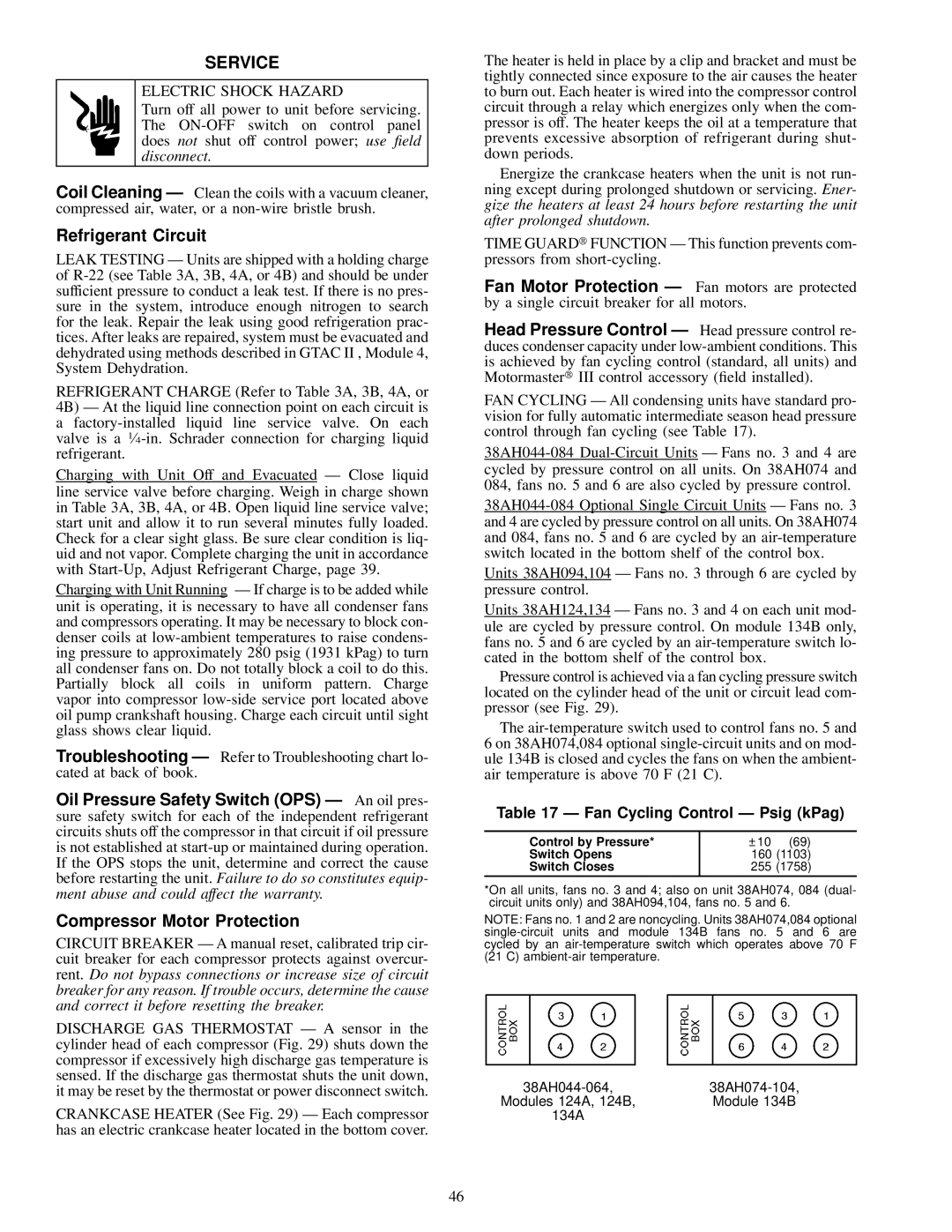
Pressure control is achieved via a fan cycling pressure switch located on the cylinder head of the unit or circuit lead com- pressor (see Fig. 29).
The air-temperature switch used to control fans no. 5 and 6 on 38AH074,084 optional single-circuit units and on mod- ule 134B is closed and cycles the fans on when the ambient- air temperature is above 70 F (21 C).
Table 17 Ð Fan Cycling Control Ð Psig (kPag)
Control by Pressure* | ± 10 (69) |
Switch Opens | 160 (1103) |
Switch Closes | 255 (1758) |
*On all units, fans no. 3 and 4; also on unit 38AH074, 084 (dual- circuit units only) and 38AH094,104, fans no. 5 and 6.
NOTE: Fans no. 1 and 2 are noncycling. Units 38AH074,084 optional single-circuit units and module 134B fans no. 5 and 6 are cycled by an air-temperature switch which operates above 70 F (21 C) ambient-air temperature.
38AH044-064,38AH074-104,
Modules 124A, 124B,Module 134B 134A