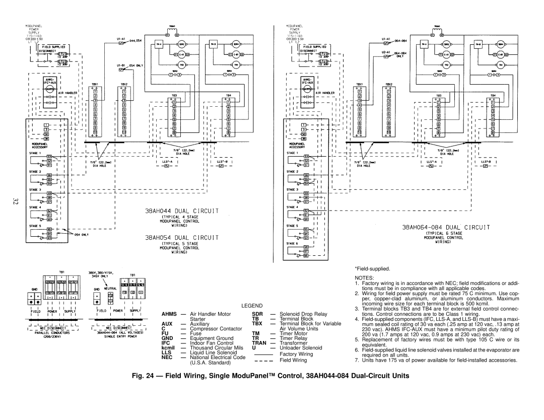
38AH044-084 specifications
The Carrier 38AH044-084 is an innovative air conditioning unit designed to provide efficient cooling solutions for residential and light commercial applications. This model is a part of Carrier's Aqua Series and is well-regarded for its combination of performance, energy efficiency, and innovative features.One of the standout characteristics of the Carrier 38AH044-084 is its high-efficiency rating, which often exceeds the minimum efficiency standards set by the Department of Energy. Its Seasonal Energy Efficiency Ratio (SEER) rating is commendable, indicating significant energy savings over traditional air conditioning units. This efficiency translates to lower utility bills and a reduced carbon footprint, making it an environmentally friendly option.
In terms of technology, the Carrier 38AH044-084 is equipped with a modern scroll compressor. This type of compressor is known for its durability and quiet operation, contributing to a more pleasant indoor environment. The unit also incorporates advanced refrigerant technology, often using R-410A refrigerant, which is recognized for its lower environmental impact compared to older refrigerants like R-22.
The design of the 38AH044-084 focuses on ease of installation and maintenance. The compact footprint makes it suitable for various installation scenarios, whether on rooftops or ground levels. Additionally, the unit is engineered for durability, featuring weather-resistant components that can withstand harsh environmental conditions.
Another notable feature is the advanced airflow system, which ensures even distribution of cooled air throughout the space. This technology minimizes hot spots and enhances overall comfort. Furthermore, the unit supports a range of thermostatic controls, allowing users to customize their cooling experience according to their specific needs.
The Carrier 38AH044-084 is also designed with noise reduction in mind. Its sound-dampening technology helps minimize operational noise, making it a suitable choice for residential areas where noise levels are a concern.
In summary, the Carrier 38AH044-084 offers an excellent combination of energy efficiency, advanced technology, and user-friendly features. Whether for a home or a light commercial space, this unit provides reliable cooling performance while maintaining a focus on environmental responsibility and occupant comfort. With its robust design and innovative capabilities, it's a solid choice for those seeking effective and efficient air conditioning solutions.

