Chapter 1 Product Overview
Switch Components
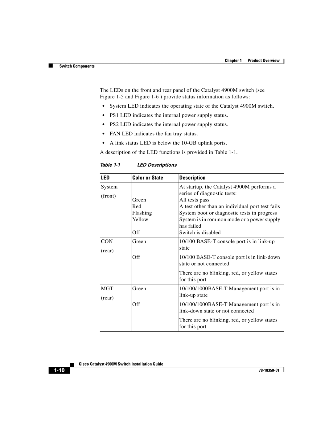
The LEDs on the front and rear panel of the Catalyst 4900M switch (see
Figure 1-5 and Figure 1-6 ) provide status information as follows:
•System LED indicates the operating state of the Catalyst 4900M switch.
•PS1 LED indicates the internal power supply status.
•PS2 LED indicates the internal power supply status.
•FAN LED indicates the fan tray status.
•A link status LED is below the 10-GB uplink ports.
A description of the LED functions is provided in Table 1-1.
Table | LED Descriptions |
| |
|
|
| |
LED | Color or State | Description | |
|
|
| |
System |
| At startup, the Catalyst 4900M performs a | |
(front) |
| series of diagnostic tests: | |
Green | All tests pass | ||
| |||
| Red | A test other than an individual port test fails | |
| Flashing | System boot or diagnostic tests in progress | |
| Yellow | System is in rommon mode or a power supply | |
|
| has failed | |
| Off | Switch is disabled | |
|
|
| |
CON | Green | 10/100 | |
(rear) |
| state | |
|
| ||
| Off | 10/100 | |
|
| state or not connected | |
|
| There are no blinking, red, or yellow states | |
|
| for this port | |
|
|
| |
MGT | Green | ||
(rear) |
| ||
|
| ||
| Off | ||
|
| ||
|
| There are no blinking, red, or yellow states | |
|
| for this port | |
|
|
|
| Cisco Catalyst 4900M Switch Installation Guide |