Chapter 3 Installing the Switch
Configurable Modules
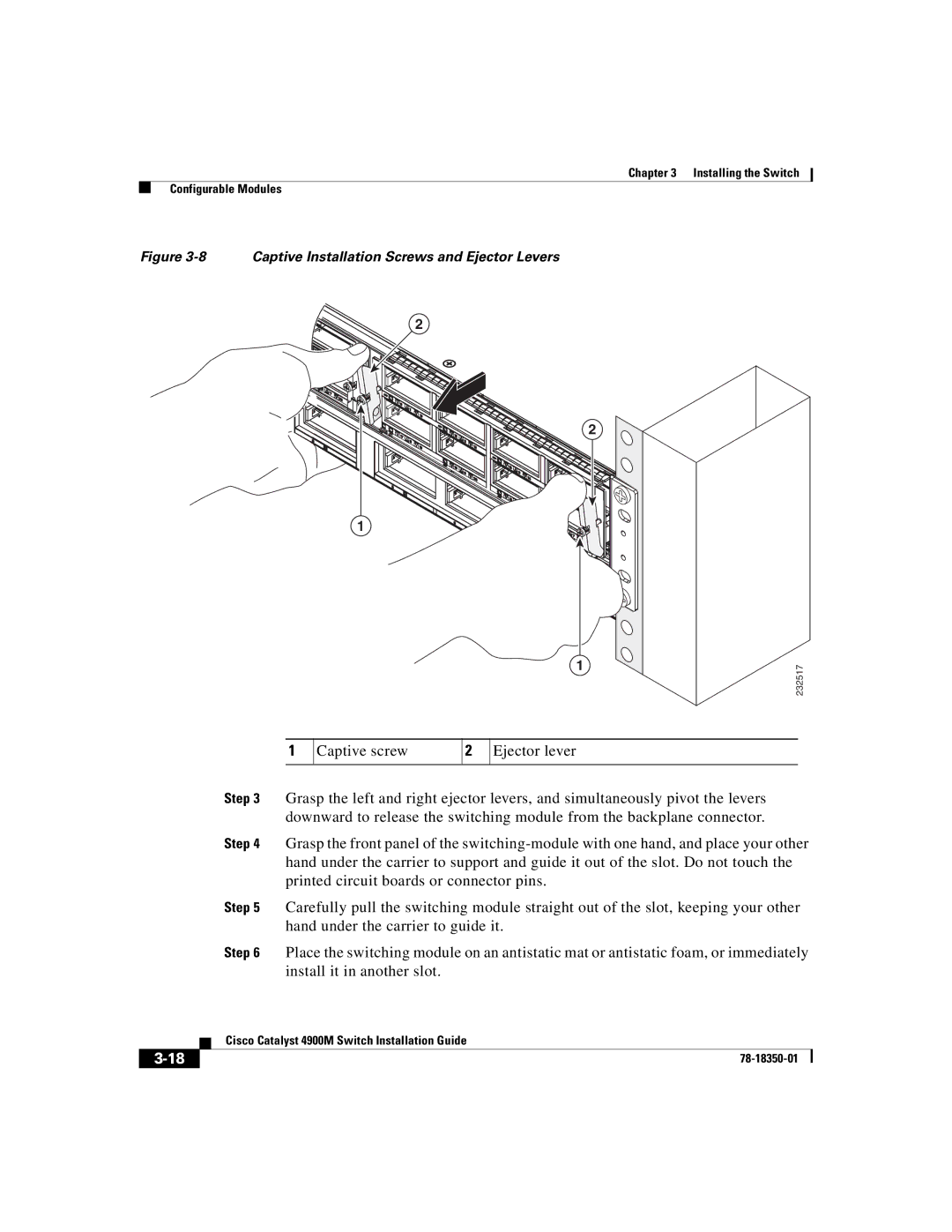
Figure 3-8 Captive Installation Screws and Ejector Levers
2
2
1
1 251732
1
Captive screw
2
Ejector lever
Step 3 Grasp the left and right ejector levers, and simultaneously pivot the levers downward to release the switching module from the backplane connector.
Step 4 Grasp the front panel of the
Step 5 Carefully pull the switching module straight out of the slot, keeping your other hand under the carrier to guide it.
Step 6 Place the switching module on an antistatic mat or antistatic foam, or immediately install it in another slot.
| Cisco Catalyst 4900M Switch Installation Guide |