Chapter 3 Installing the Switch
Configurable Modules
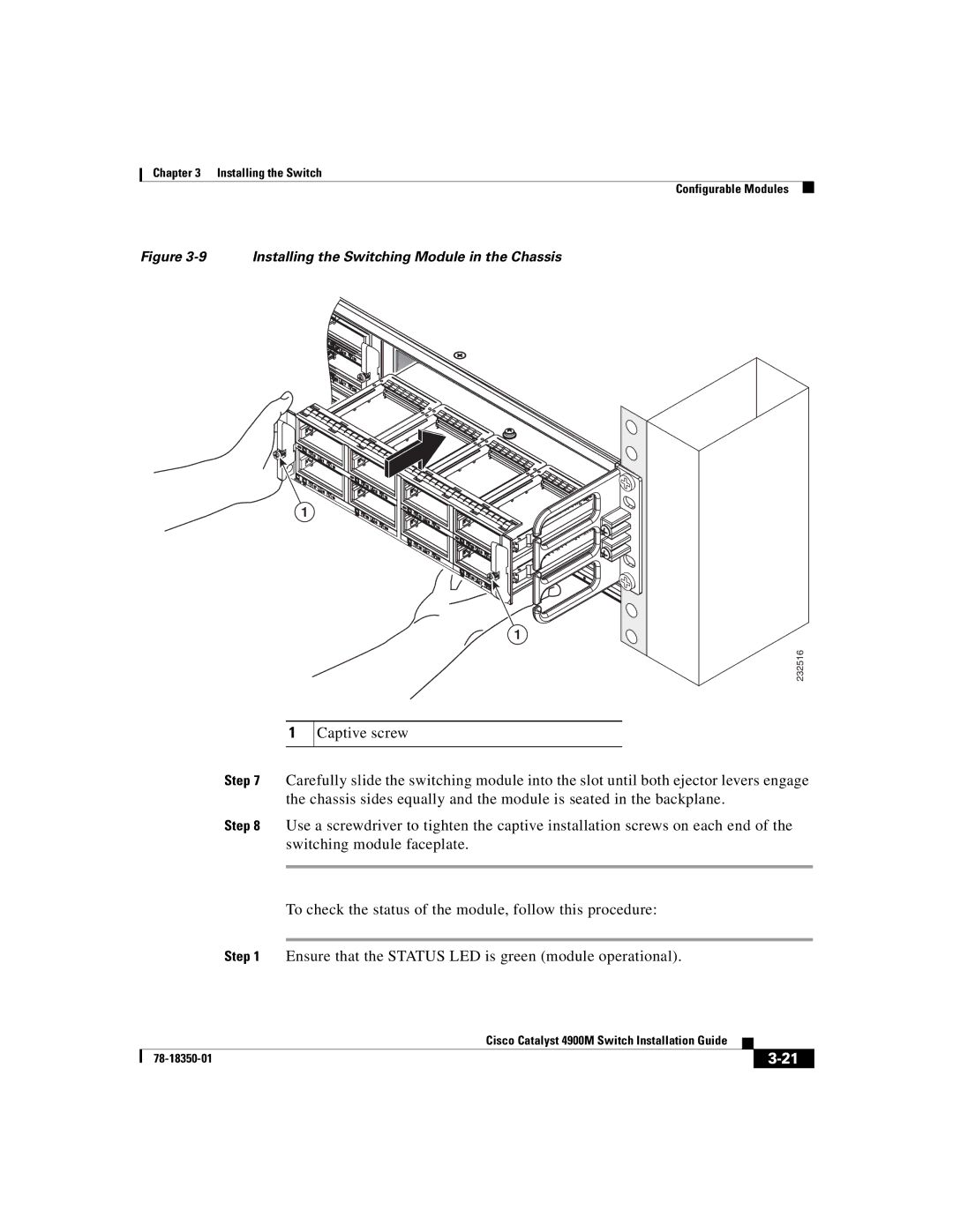
Figure 3-9 Installing the Switching Module in the Chassis
1
1
232516
1
Captive screw
Step 7 Carefully slide the switching module into the slot until both ejector levers engage the chassis sides equally and the module is seated in the backplane.
Step 8 Use a screwdriver to tighten the captive installation screws on each end of the switching module faceplate.
To check the status of the module, follow this procedure:
Step 1 Ensure that the STATUS LED is green (module operational).
|
| Cisco Catalyst 4900M Switch Installation Guide |
|
|
|
|
| ||
|
|
| ||
|
|
|
