Corporate Headquarters
Cisco 7401ASR Installation and Configuration Guide
Cisco 7401ASR Installation and Configuration Guide
Iii
N T E N T S
Using the Cable-Management Bracket
Troubleshooting
Using the show pxf feature ? Command and Subcommands B-6
Vii
Product Description C-2
Viii
Audience
Preface
Chapter Title Description
Organization
Document Conventions
Indicates a comment line
Default responses to system prompts are in square brackets
You press the D key
Xii
Waarschuwing Belangrijke Veiligheidsinstructies
Hinweis Bewahren SIE Diese Sicherheitsanweisungen AUF
Warnung Wichtige Sicherheitsanweisungen
Figyelem! Fontos Biztonsági Elõírások
Megjegyzés Õrizze MEG Ezeket AZ Utasításokat
Xiv
Aviso Instruções Importantes DE Segurança
Terms and Acronyms
Xvi
Obtaining Documentation
Related Documentation
Cisco.com
Ordering Documentation
Obtaining Technical Assistance
Documentation Feedback
Cisco Technical Support Website
You can order Cisco documentation in these ways
Xix
Submitting a Service Request
Definitions of Service Request Severity
Obtaining Additional Publications and Information
Hardware Overview
Overview and Parts Installation
Cisco 7401ASR Router-Front View
Front View
LEDs
Power Up
LED Label
Color State, the LED is Traffic
System Board
Rear View
Checking the Shipping Container Contents
Verified Task Date
Installation Checklist
Installing and Removing the CompactFlash Disk
Installing the CompactFlash Disk, GBIC, and Port Adapter
Gigabit Interface Converter-GBIC
Installing and Removing the Gigabit Interface Converter
57603
Installing a Port Adapter or Service Adapter
Installing and Removing a Port Adapter or Service Adapter
Replacing the Sdram Dimm
Removing the Cover
Black zinc coating, as a replacement
Cover screws Cover removal slot and flatblade screwdriver
Remove the four screws holding the cover to the chassis
Dimm
Removing and Installing the Sdram Dimm
Spring latch on Dimm socket
Replacing the Cover
Preparing to Install the Cisco 7401ASR Router
Rack-Mounting, Tabletop Installation, Cabling
Cisco 7401ASR
Tools and Parts Required
Electrical Equipment Guidelines
Preventing Electrostatic Discharge Damage
Safety Guidelines
Electrostatic Discharge Prevention
Site Requirement Guidelines
General Tabletop or Workbench Installation
Installing the Router
Rack-Mounting a Cisco 7401ASR Router
Locate the threaded holes in the front sides of the chassis
Attaching the Cable-Management Bracket
Installing Rack-Mount Brackets on the Rear of the Chassis
Installing the Chassis in the Rack
Installing the Cisco 7401ASR Router in a Two-Post Rack
Two-Post Rack Installation
Attaching a Chassis Ground Connection
Four-Post Rack Installation
Locating the Chassis Grounding Connector
Fan vents Ground connector
Attaching a Grounding Lug to the Chassis Grounding Connector
Connecting Port Adapter Cables
Adapter DTE M/F Pins DCE M/F Pins Mmod Pins
Connecting I/O Cables
Connecting Console and Auxiliary Port Cables
Mmod
Fdte
Fdce
Intra-Building Lightning Protection
Attaching the Fast Ethernet/Ethernet 10/100 Cables
Attaching Multimode and Single-Mode Optical Fiber Cables
Attaching the Gbic Interface Cables
Description Operating Distance
Product Number
GBIC-SX=
GBIC-LX/LH=
13 Gbic Port Connections
Mode-Conditioning Patch Cord Description
Cisco 7401ASR Installation and Configuration Guide
Attaching the Mode-Conditioning Patch Cord
Using the Cable-Management Bracket
Attaching the Alarm Port Cable
Connecting AC-Input Power
Connecting Power
Connecting DC-Input Power
OL-5419-01 B0
OL-5419-01 B0
Chassis Slot and Logical Interface Numbering
Functional Overview
Router# show interface g1/0
Router# show interfaces
Online Insertion and Removal
MAC Address
Environmental Monitoring
Environmental Monitoring and Reporting Functions
Parameter High Warning High Critical Shutdown
Reporting Functions
PXF
CPU
Router# show environment all
Router# show environment last
Router# show environment table
With a single 48V DC power supply installed
With a single 24V DC power supply installed
Fan Failures
With dual 48V DC power supplies installed
Starting the System and Observing Initial Conditions
Checking Conditions Prior to System Startup
Configuring a Cisco 7401ASR Router
Hostname# copy running-config startup-config
Performing a Basic Configuration Using AutoInstall
Performing a Basic Configuration Using the Setup Facility
Restricted Rights Legend
Configuring Global Parameters
Enter enable secret barney
Enter enable secret, enable, and virtual terminal passwords
Configure RIP routing? no
Example
Following speed/duplex settings are supported
Interface counters may be cleared reset by using the command
Configuring Port Adapter Interfaces
Configuring Fast Ethernet Interfaces
Configuring Synchronous Serial Interfaces
Turn off IPX to prevent network conflicts. interface ATM1/0
Connect a console terminal to the console port
Configuration changes can only be made in enable mode
Router
Prompt changes to the privileged Exec prompt
Checking the Running Configuration Settings
Performing Other Configuration Tasks
Saving the Running Configuration to Nvram
Overview of the Password Recovery Procedure
Replacing or Recovering a Lost Password
Details of the Password Recovery Procedure
Change all three passwords using the following commands
Boot images
Viewing Your System Configuration
Release 12.21DD
Router# show version
Show diag
Performing Complex Configurations
OL-5419-01 B0
Overview
Configuration Tasks
Configuring IKE
Using the Exec Command Interpreter
Creating Crypto Access Lists
Configuring IPSec
Defining Transform Sets
Command Purpose
Creating Crypto Map Entries
Verifying the Configuration
Currentpeer 172.21.114.67 PERMIT, flags=originisacl
OL-5419-01 B0
Troubleshooting Overview
Troubleshooting
Action Yes
Problem Solving Using a Subsystems Approach
Identifying Startup Problems
Symptom Possible Cause Possible Solution
Troubleshooting the Power Subsystem
Command to display the internal chassis
Troubleshooting the Cooling Subsystem
To determine if the fans are operating, listen
System shuts down, use the show
Troubleshooting the Port Adapter or Service Adapter
Troubleshooting the I/O Subsystem
Troubleshooting the Processor Subsystem
Router# copy tftp bootflash
Upgrading the Boot Helper Boot Loader Image
Router# format bootflash
Features Not Supported by PXF
PXF Troubleshooting Information
Cisco IOS Statistics Not Supported by PXF
High PXF CPU Usage
Router# show interfaces serial 0/0
Ignored Packets
Router# show interfaces ethernet 0/0
No Buffers
Priority and Policing Configured in the Class Policy
PXF Punts
QoS Fast-send and QoS Enqueue
Description Specification
System Specifications
Software Requirements
Memory Specifications and Configurations
Processor Specifications
Minimum Maximum Power Budget
Transmit Power Receive Power
Gbic Cabling and Connection Equipment
GBIC-SX= or DBm 17 dBm WS-G5484=
GBIC-LX/LH or WS-G5486
GBIC-SX or WS-G5484
Wave Length Core Size
Fiber Type Micron MHz/km Cable Distance
GBIC-ZX or WS-G5487
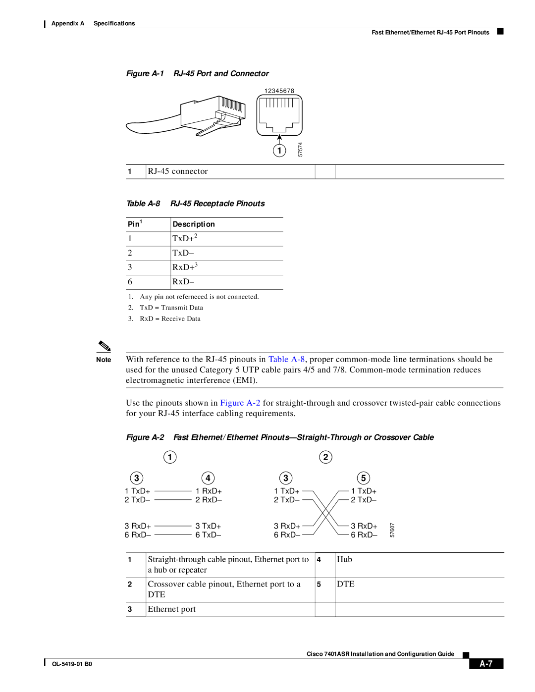
Fast Ethernet/Ethernet RJ-45 Port Pinouts
DTE
Pin Description
Pin Signal Direction Description
Console and Auxiliary Port Signals and Pinouts
Lithium Battery Caution
Alarm Port
Valmistajan ohjeiden mikaisesti
Kasseres i henhold til fabrikantens instruksjoner
OL-5419-01 B0
PXF Information
Using show Commands
Using the show version Command
Using the show c7400 Command
Using the show pxf Commands
Router# show pxf accounting ?
Using the show pxf accounting ? Command and Subcommands
Router#show pxf crash
Using the show pxf crash Command
Router# show pxf accounting POS4/0
Using the show pxf interface Command
Using the show pxf info Command
Using the show pxf feature ? Command and Subcommands
Router# show pxf feature ?
Feature Nat ?
Router# show pxf feature cef ? entry
Router# show pxf feature nat entry
Router# show pxf feature nat stat
OL-5419-01 B0
Tools and Parts Required
Hardware and Software Requirements
Memory Size Product Number
Product Description
64 MB
MEM-COMP-FLD64M=
System Memory and Software Image Functions and Interactions
Compatibility Requirements
Boot Environment Variables
This section includes the following subsections
Sample Upgrade Process
Working with a CompactFlash Disk
Command and Arguments Purpose
Software Command Overview
Using Software Commands
System# cd disk0
Using the cd Command
Using the show Command
Using the format Command
Using the pwd Command
Using the dir Command
System# mkdir disk0dailydir
Using the mkdir Command
Router# format disk0
Using the delete Command
Using the rmdir Command
Delete the file fun1
System# rmdir disk0dailydir
Verify that the file fun1 is deleted
Enabling Booting from a CompactFlash Disk
Crtl-Z
System# copy systemrunning-config nvramstartup-config
System# config terminal
OL-5419-01 B0
Bit No Hex Meaning
Configuration Bit Meanings
Following information is found in this appendix
Boots the boot helper image as a system image
Boot Field Meaning
Bits
Tftp flash filename
Action/File Name Bit
Bit
Bit 11 and Bit
Bit 10 and Bit
Bit IP Address net host
Baud Bit
Router# show version
Setting the Configuration Register While Running Cisco IOS
Enable
OL-5419-01 B0
IN-1
D E
Initialization-vector size
Cisco IOS Cisco 7401ASR requirements Documentation
Show version
IN-2
Interface parameters Sample configuration
ATM interfaces AutoInstall Basic router Examples
Igrp IKE
Eeprom
IN-4
Gbic
Igrp
IN-5
IPX
IN-6
OIR
IN-7
RIP
VAM
Snmp
LED
IN-8
IN-9
Safety information