Chapter 5 Removal and Replacement Procedures
Removing and Replacing the Power Supply
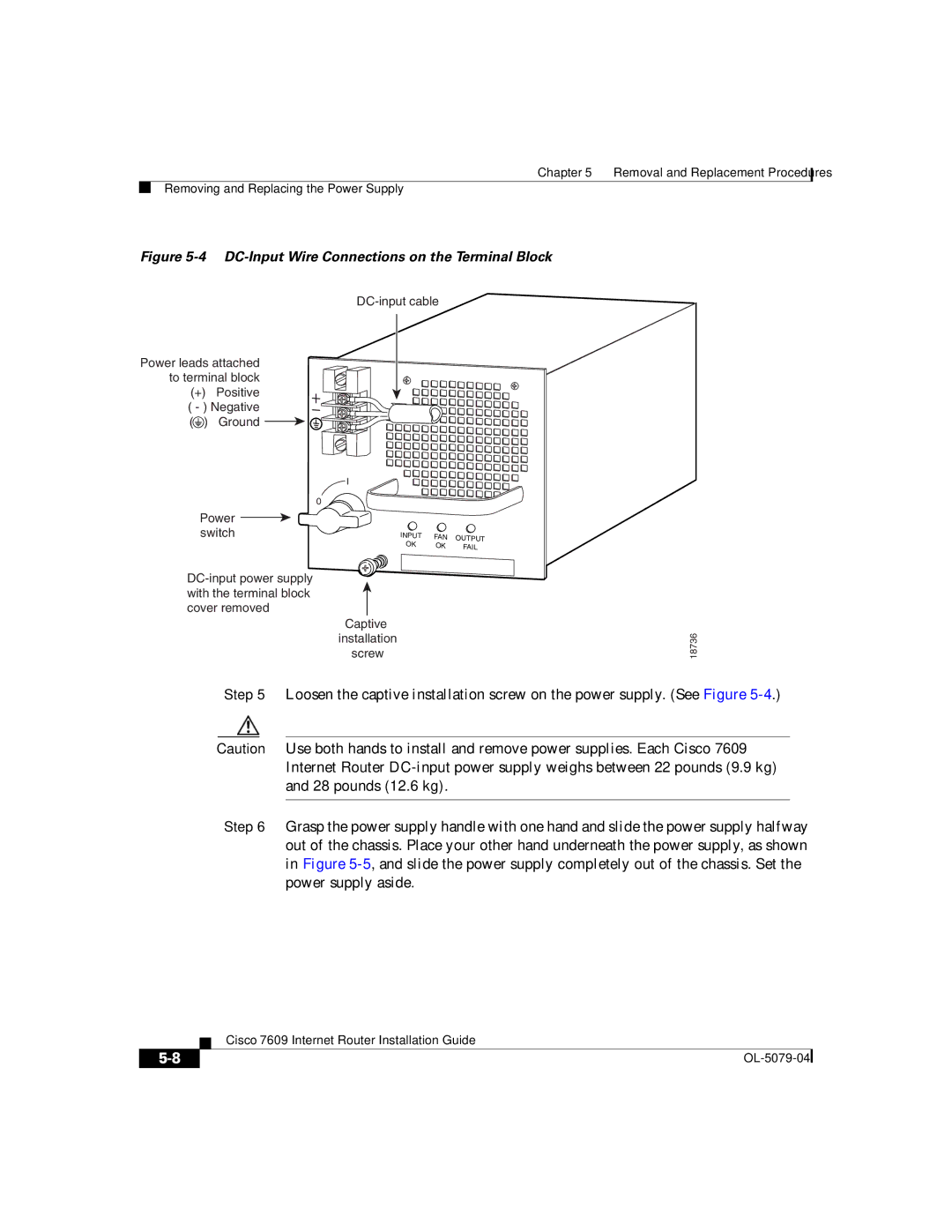
Figure 5-4 DC-Input Wire Connections on the Terminal Block
Power leads attached to terminal block
(+) Positive
( - ) Negative
(![]() ) Ground
) Ground ![]()
![]()
![]() I
I
0
Power
switch | INPUT | FAN | OUTPUT |
| OK | OK | |
| FAIL | ||
|
|
|
Captive installation screw
18736
Step 5 Loosen the captive installation screw on the power supply. (See Figure
Caution Use both hands to install and remove power supplies. Each Cisco 7609 Internet Router
Step 6 Grasp the power supply handle with one hand and slide the power supply halfway out of the chassis. Place your other hand underneath the power supply, as shown in Figure
| Cisco 7609 Internet Router Installation Guide |
|