Appendix B Connecting a Modem to the GSS Console Port
Configuring a Modem
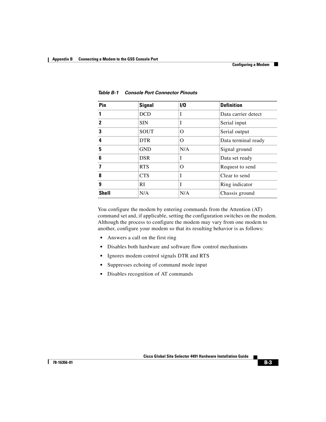
Table B-1 Console Port Connector Pinouts
Pin | Signal | I/O | Definition |
|
|
|
|
1 | DCD | I | Data carrier detect |
|
|
|
|
2 | SIN | I | Serial input |
|
|
|
|
3 | SOUT | O | Serial output |
|
|
|
|
4 | DTR | O | Data terminal ready |
|
|
|
|
5 | GND | N/A | Signal ground |
|
|
|
|
6 | DSR | I | Data set ready |
|
|
|
|
7 | RTS | O | Request to send |
|
|
|
|
8 | CTS | I | Clear to send |
|
|
|
|
9 | RI | I | Ring indicator |
|
|
|
|
Shell | N/A | N/A | Chassis ground |
|
|
|
|
You configure the modem by entering commands from the Attention (AT) command set and, if applicable, setting the configuration switches on the modem. Although the process to configure the modem may vary from one modem to another, configure your modem so that its resulting behavior is as follows:
•Answers a call on the first ring
•Disables both hardware and software flow control mechanisms
•Ignores modem control signals DTR and RTS
•Suppresses echoing of command mode input
•Disables recognition of AT commands
|
| Cisco Global Site Selector 4491 Hardware Installation Guide |
|
|
|
|
| ||
|
|
| ||
|
|
|