Chapter 1 Introduction
Ports and Connectors
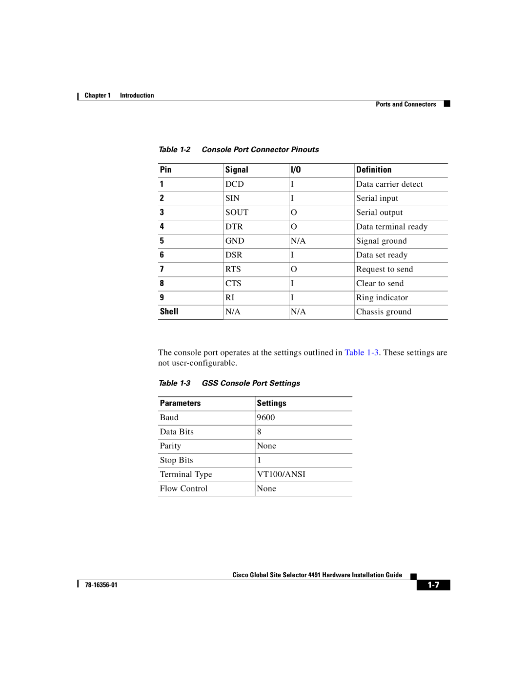
Table
Pin | Signal | I/O | Definition |
|
|
|
|
1 | DCD | I | Data carrier detect |
|
|
|
|
2 | SIN | I | Serial input |
|
|
|
|
3 | SOUT | O | Serial output |
|
|
|
|
4 | DTR | O | Data terminal ready |
|
|
|
|
5 | GND | N/A | Signal ground |
|
|
|
|
6 | DSR | I | Data set ready |
|
|
|
|
7 | RTS | O | Request to send |
|
|
|
|
8 | CTS | I | Clear to send |
|
|
|
|
9 | RI | I | Ring indicator |
|
|
|
|
Shell | N/A | N/A | Chassis ground |
|
|
|
|
The console port operates at the settings outlined in Table
Table
Parameters | Settings |
|
|
Baud | 9600 |
|
|
Data Bits | 8 |
|
|
Parity | None |
|
|
Stop Bits | 1 |
|
|
Terminal Type | VT100/ANSI |
|
|
Flow Control | None |
|
|
|
| Cisco Global Site Selector 4491 Hardware Installation Guide |
|
|
|
|
| ||
|
|
| ||
|
|
|
