Chapter 1 Overview
Back Panel Ports and LEDs
Back Panel Ports and LEDs
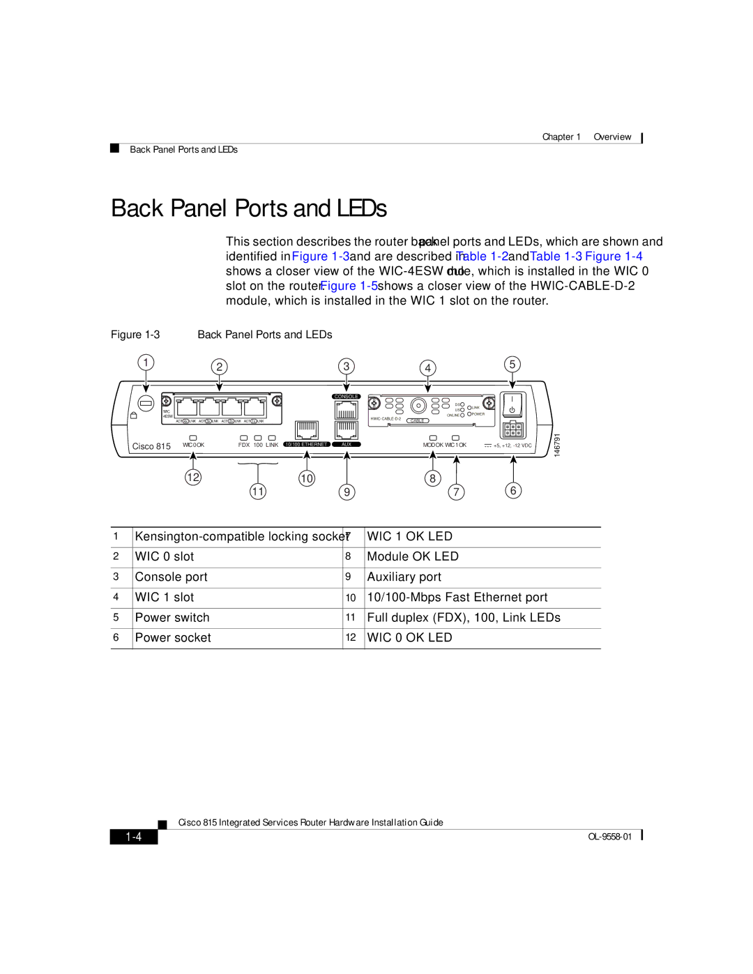
This section describes the router back panel ports and LEDs, which are shown and identified in Figure
Figure | Back Panel Ports and LEDs |
|
|
| ||
1 |
| 2 | 3 |
| 4 | 5 |
|
|
| CONSOLE |
|
|
|
|
|
|
|
| DS | LINK |
WIC |
|
|
|
| US | |
|
|
|
|
| ||
|
|
|
| ONLINE | POWER | |
4ESW |
|
|
| |||
|
|
| CABLE |
| ||
| ACT 4x LNK ACT 3x LNK ACT 2x LNK ACT 1x LNK |
|
| |||
|
|
|
| |||
Cisco 815 | WIC0OK | FDX 100 LINK | 10/100 ETHERNET AUX |
| MODOK WIC1OK | +5, +12, |
| 12 |
| 10 |
| 8 | 6 |
|
| 11 | 9 |
| 7 | |
146791
1 | 7 | WIC 1 OK LED | |
|
|
|
|
2 | WIC 0 slot | 8 | Module OK LED |
|
|
|
|
3 | Console port | 9 | Auxiliary port |
|
|
|
|
4 | WIC 1 slot | 10 | |
|
|
|
|
5 | Power switch | 11 | Full duplex (FDX), 100, Link LEDs |
|
|
|
|
6 | Power socket | 12 | WIC 0 OK LED |
|
|
|
|
| Cisco 815 Integrated Services Router Hardware Installation Guide |