Chapter 2 Installation
Optional Installation Procedures
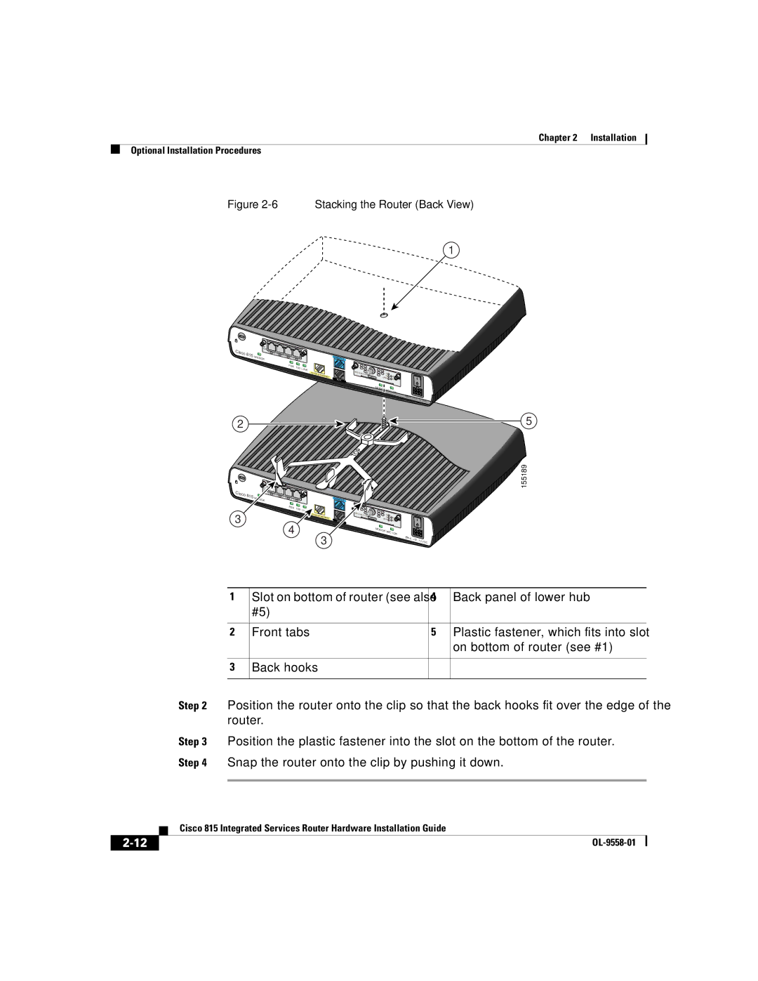
Figure 2-6 Stacking the Router (Back View)
1
|
| WIC |
|
|
|
|
|
|
|
|
|
|
|
|
|
|
|
Cisco |
| 4ESW |
| LNK | ACT |
|
|
|
|
|
|
|
|
|
|
|
|
815 |
| ACT 4x |
|
| ACT 2x |
|
|
|
|
|
|
|
|
| |||
| WIC0OK |
|
|
| 3x | LNK | LNK ACT 1x LNK |
|
| CONSOLE |
|
|
|
| |||
|
|
|
|
|
|
|
|
|
|
|
|
|
| ||||
|
|
|
|
|
|
|
|
| FDX | 100 | LINK |
|
|
|
|
|
|
|
|
|
|
|
|
|
|
|
|
|
|
|
|
|
| ||
|
|
|
|
|
|
|
|
|
|
|
|
| HWIC- |
|
|
| |
|
|
|
|
|
|
|
|
|
|
| 10/100 E | THER |
| DS |
| ||
|
|
|
|
|
|
|
|
|
|
|
|
|
| ||||
|
|
|
|
|
|
|
|
|
|
|
| NET |
| CABLE | US | LINK | |
|
|
|
|
|
|
|
|
|
|
|
|
|
| ONLINE |
| ||
|
|
|
|
|
|
|
|
|
|
|
|
| AUX |
|
|
| POWER |
|
|
|
|
|
|
|
|
|
|
|
|
|
|
|
| MODOK |
|
|
|
|
|
|
|
|
|
|
|
|
|
|
|
|
| WIC | |
|
|
|
|
|
|
|
|
|
|
|
|
|
|
|
|
| 1OK |
+5, + |
|
12, | VDC |
|
2
Cisco 815
3
WIC |
|
|
|
|
|
4ESW |
|
|
|
|
|
ACT 4x | LNK | ACT |
|
|
|
WIC0OK |
| 3x LNK | ACT 2x | LNK ACT 1x LNK | |
|
|
| |||
|
|
|
| FDX | 100 L |
|
|
|
|
| |
CONSOLE
10/100 | ETH |
| ERNET |
| AUX |
![]()
![]()
![]()
CABLE
DS |
|
US | LINK |
ONLINE | POWER |
5
155189
4 |
| MODOK W | IC1OK |
|
3 |
|
| ||
|
| +5, + |
| |
|
|
| 12, | VDC |
1 | Slot on bottom of router (see also | 4 | Back panel of lower hub |
| #5) |
|
|
|
|
|
|
2 | Front tabs | 5 | Plastic fastener, which fits into slot |
|
|
| on bottom of router (see #1) |
|
|
|
|
3 | Back hooks |
|
|
|
|
|
|
Step 2 Position the router onto the clip so that the back hooks fit over the edge of the router.
Step 3 Position the plastic fastener into the slot on the bottom of the router. Step 4 Snap the router onto the clip by pushing it down.
| Cisco 815 Integrated Services Router Hardware Installation Guide |
