Chapter 2 Getting Started
Installing the Cisco Video Surveillance IP Camera
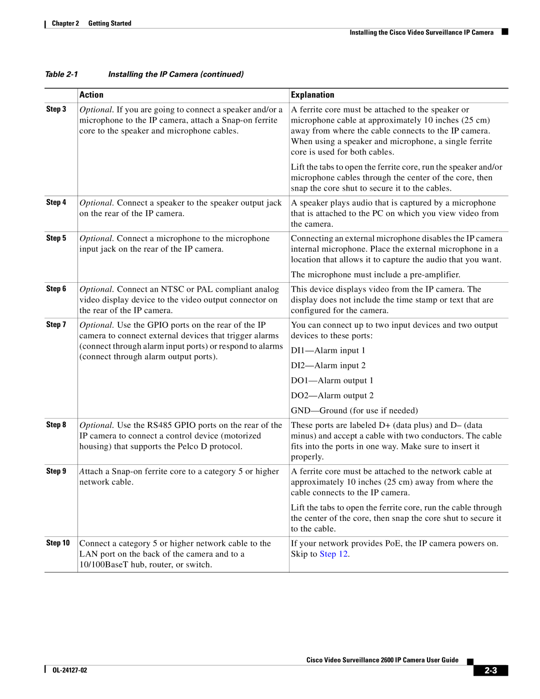
Table | Installing the IP Camera (continued) |
|
|
|
|
| Action | Explanation |
|
|
|
Step 3 | Optional. If you are going to connect a speaker and/or a | A ferrite core must be attached to the speaker or |
| microphone to the IP camera, attach a | microphone cable at approximately 10 inches (25 cm) |
| core to the speaker and microphone cables. | away from where the cable connects to the IP camera. |
|
| When using a speaker and microphone, a single ferrite |
|
| core is used for both cables. |
|
| Lift the tabs to open the ferrite core, run the speaker and/or |
|
| microphone cables through the center of the core, then |
|
| snap the core shut to secure it to the cables. |
|
|
|
Step 4 | Optional. Connect a speaker to the speaker output jack | A speaker plays audio that is captured by a microphone |
| on the rear of the IP camera. | that is attached to the PC on which you view video from |
|
| the camera. |
|
|
|
Step 5 | Optional. Connect a microphone to the microphone | Connecting an external microphone disables the IP camera |
| input jack on the rear of the IP camera. | internal microphone. Place the external microphone in a |
|
| location that allows it to capture the audio that you want. |
|
| The microphone must include a |
|
|
|
Step 6 | Optional. Connect an NTSC or PAL compliant analog | This device displays video from the IP camera. The |
| video display device to the video output connector on | display does not include the time stamp or text that are |
| the rear of the IP camera. | configured for the camera. |
|
|
|
Step 7 | Optional. Use the GPIO ports on the rear of the IP | You can connect up to two input devices and two output |
| camera to connect external devices that trigger alarms | devices to these ports: |
| (connect through alarm input ports) or respond to alarms | |
| (connect through alarm output ports). | |
|
| |
|
| |
|
| |
|
| |
|
|
|
Step 8 | Optional. Use the RS485 GPIO ports on the rear of the | These ports are labeled D+ (data plus) and D– (data |
| IP camera to connect a control device (motorized | minus) and accept a cable with two conductors. The cable |
| housing) that supports the Pelco D protocol. | fits into the ports in one way. Make sure to insert it |
|
| properly. |
|
|
|
Step 9 | Attach a | A ferrite core must be attached to the network cable at |
| network cable. | approximately 10 inches (25 cm) away from where the |
|
| cable connects to the IP camera. |
|
| Lift the tabs to open the ferrite core, run the cable through |
|
| the center of the core, then snap the core shut to secure it |
|
| to the cable. |
|
|
|
Step 10 | Connect a category 5 or higher network cable to the | If your network provides PoE, the IP camera powers on. |
| LAN port on the back of the camera and to a | Skip to Step 12. |
| 10/100BaseT hub, router, or switch. |
|
|
|
|
Cisco Video Surveillance 2600 IP Camera User Guide
|
| ||
|
|
