Chapter 3 Power Supply Installation
Warning This product relies on the building’s installation for
AC: 5 A, DC: 15 A Statement 1005
Warning A readily accessible
Warning Only trained and qualified personnel should be allowed to install or replace this equipment. Statement 1030
Warning Hazardous voltage or energy may be present on power terminals. Always replace cover when terminals are not in service. Be sure uninsulated conductors are not accessible when cover is in place. Statement 1086
Step 1 Locate the AC and DC circuit breakers, turn them OFF, and tape them in the OFF position.
Note Do not connect the switch to a power source that has an ON/OFF switch.
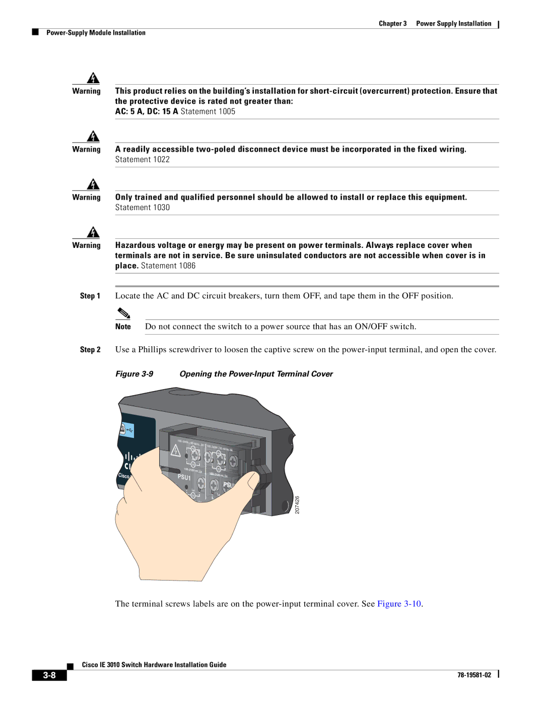
Step 2 Use a Phillips screwdriver to loosen the captive screw on the
Figure 3-9 Opening the Power-Input Terminal Cover
Cisco CGS 2520
100- |
|
|
|
|
240V~, 50- |
|
| ||
|
| 60Hz, 2A | 100- |
|
|
|
| 240V~, 50- | |
|
|
|
| 60Hz, 2A |
| 5 | 2A |
|
|
|
| 5 |
| |
|
|
| 2A | |
|
|
|
| |
|
| 10A |
|
|
|
|
|
| 10A |
![]() 207426
207426
The terminal screws labels are on the
Cisco IE 3010 Switch Hardware Installation Guide
| ||
|