Chapter 3 Power Supply Installation
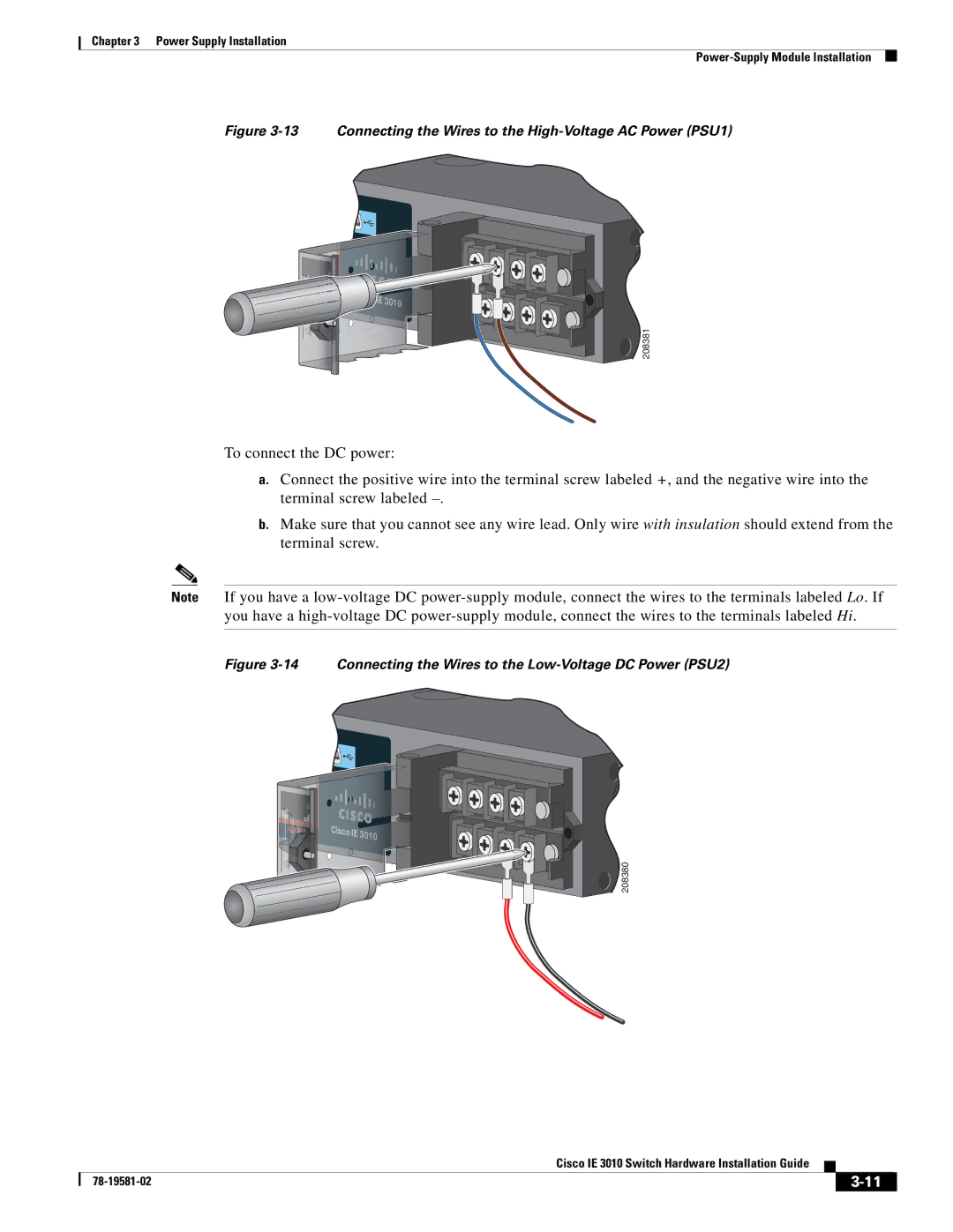
Figure 3-13 Connecting the Wires to the High-Voltage AC Power (PSU1)
Cisco IEE | 30 |
| 010 |
![]() 208381
208381
To connect the DC power:
a.Connect the positive wire into the terminal screw labeled +, and the negative wire into the terminal screw labeled
b.Make sure that you cannot see any wire lead. Only wire with insulation should extend from the terminal screw.
Note If you have a
Figure 3-14 Connecting the Wires to the Low-Voltage DC Power (PSU2)
Cisco IE 30110
![]() 208380
208380
Cisco IE 3010 Switch Hardware Installation Guide
|
| ||
|
|