Chapter
Rack Specifications and Recommendations
The SFS 7012 switch is designed to be installed in an existing
The SFS 7012 switch is designed for a
Racks should conform to conventional standards. In the United States, use American National Standards Institute (ANSI)/Electronic Industries Association (EIA) standard
•Racks should meet the following mechanical recommendations:
–
–Universal mounting rail hole pattern identified in IEC Standard 297
–Mounting holes flush with the rails to accommodate the switch
•Use a rack grounding kit and a ground conductor that is carried back to earth or to another suitable building ground. Ground the equipment rack to earth ground.
•Provide enough room to work on the equipment. Clear the work site of any unnecessary materials. Make sure the equipment will have enough clearance for front and rear access.
Installing and Routing Cable
Note Building and electrical codes vary depending on the location. Comply with all code specifications when planning the site and installing cable.
When running cables to the equipment, consider the following:
•Do not run cables where they can be stepped on or rolled over.
•Be sure cables are intact with no cuts, bends, or nicks.
•Provide proper strain relief for standard IB cables by adhering to the following guidelines:
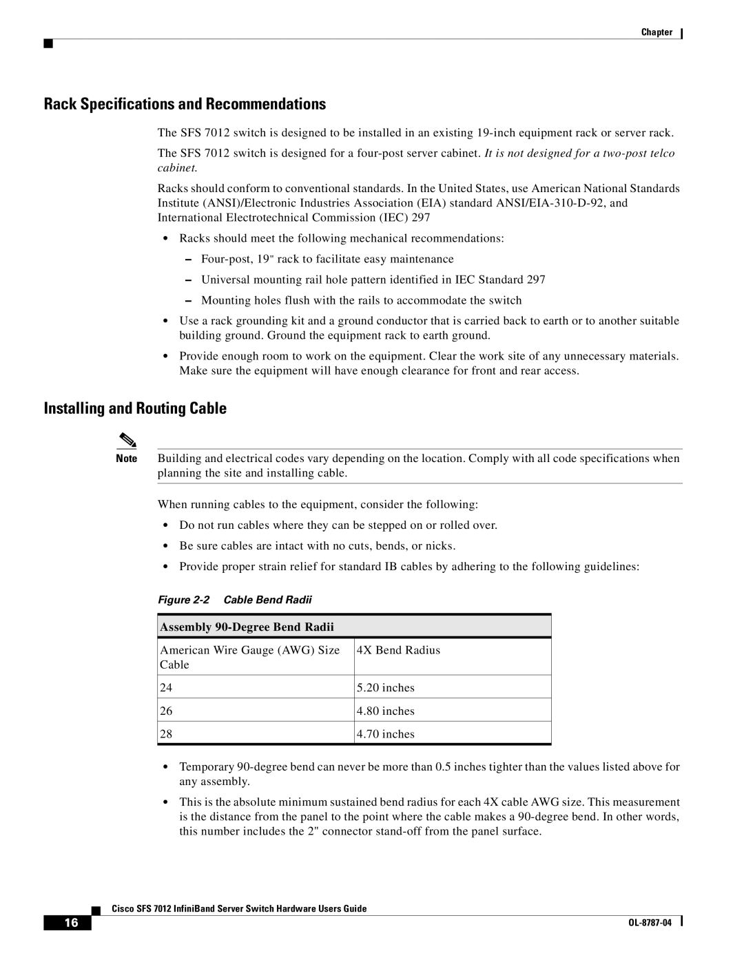
Figure 2-2 Cable Bend Radii
Assembly 90-Degree Bend Radii
American Wire Gauge (AWG) Size | 4X Bend Radius |
Cable |
|
|
|
24 | 5.20 inches |
|
|
26 | 4.80 inches |
|
|
28 | 4.70 inches |
|
|
•Temporary
•This is the absolute minimum sustained bend radius for each 4X cable AWG size. This measurement is the distance from the panel to the point where the cable makes a
Cisco SFS 7012 InfiniBand Server Switch Hardware Users Guide
16 |
|
|
|