Chapter
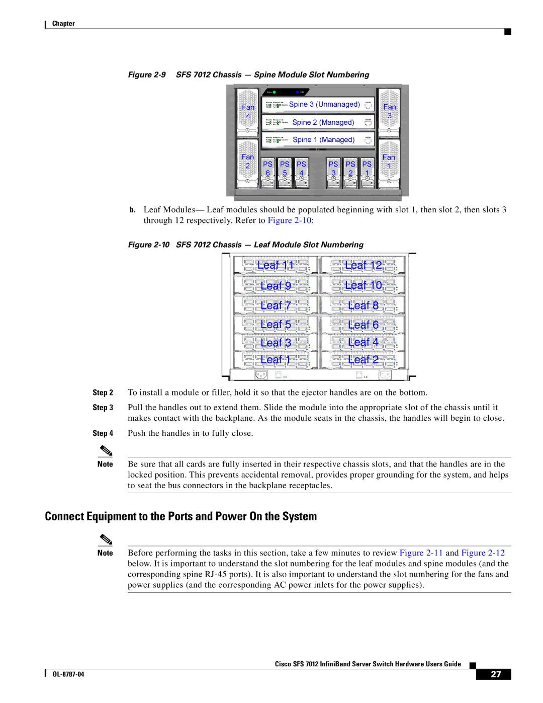
Figure 2-9 SFS 7012 Chassis — Spine Module Slot Numbering
b.Leaf Modules— Leaf modules should be populated beginning with slot 1, then slot 2, then slots 3 through 12 respectively. Refer to Figure
|
|
| Figure | |
|
|
| Leaf 11 | Leaf 12 |
|
|
| Leaf 9 | Leaf 10 |
|
|
| Leaf 7 | Leaf 8 |
|
|
| Leaf 5 | Leaf 6 |
|
|
| Leaf 3 | Leaf 4 |
|
|
| Leaf 1 | Leaf 2 |
Step 2 | To install a module or filler, hold it so that the ejector handles are on the bottom. | |||
Step 3 | Pull the handles out to extend them. Slide the module into the appropriate slot of the chassis until it | |||
|
|
| makes contact with the backplane. As the module seats in the chassis, the handles will begin to close. | |
Step 4 | Push the handles in to fully close. |
| ||
|
|
|
| |
| Note | Be sure that all cards are fully inserted in their respective chassis slots, and that the handles are in the | ||
|
|
| locked position. This prevents accidental removal, provides proper grounding for the system, and helps | |
|
|
| to seat the bus connectors in the backplane receptacles. |
|
|
|
|
|
|
Connect Equipment to the Ports and Power On the System
Note Before performing the tasks in this section, take a few minutes to review Figure
Cisco SFS 7012 InfiniBand Server Switch Hardware Users Guide
| 27 |
| |
|
|