Intel Pentium 4 Processor Intel 850 Chipset
Technical Reference Guide
Page
TRG
Page
Reader Feedback
Page
Technical Reference Guide
First Edition -- December
Table of Contents
Parallel Interface Connector
Power Supply and Distribution
Appendix B Ascii Character SET
Appendix D COMPAQ/NVIDIA TNT2 PRO AGP Graphics Card
Appendix H COMPAQ/MATROX Millennium G450 AGP Graphics Card
Appendix L COMPAQ/ADAPTEC Scsi Host Adapter
List of Figures
Figure C-1. Keystroke Processing ELEMENTS, Block Diagram
Figure L-3. External Ultra Scsi Connector 50-PIN
List of Tables
Technical Reference Guide
Able H-3
This page is intentionally blank
Additional Information Sources
Using this Guide
Introduction
About this Guide
BIT Notation
Signal Labels
Notational Conventions
Register Notation and Usage
Common Acronyms and Abbreviations
Acronyms and Abbreviations
Acronym/Abbreviation Description
DMA
Dimm
DIN
DIP
LIF
LAN
LCD
LED
Secam
Scsi
Sdram
SEC
Introduction
System Overview
Deskpro EXS Deskpro Workstation
Features and Options
Standard Features
Standard Feature Difference Matrix
Options
Deskpro EXS Deskpro Workstation
Mechanical Design
Cabinet Layouts
Front Views
Rear View
Shows the rear cabinet layout of the controls and connectors
Chassis Layout
Back
Front
System Board Layout
Board Layout
System Architecture
MCH AGP Rdram
ICH2 LPC
FWH
Pentium 4 Processor
Support Component Functions
Chipset
Support Components
Chipset Comparison
Universal Serial BUS Interface
System Memory
Mass Storage
SERIAL, Parallel Interfaces
G450
Graphics Subsystem
Standard AGP Graphics Card Comparison
Matrox
Audio Subsystem
Specifications
Environmental Specifications Factory Configuration
Electrical Specifications
Compaq SP#
Physical Specifications
Diskette Drive Specifications
Parameter Desktop Configuration Minitower Configuration
Parameter 18.0 GB 20.0 GB 40.0 GB
48x CD-ROM Drive Specifications SP# 187217-B21
Hard Drive Specifications
Parameter Measurement
XMM1 XMM2 Rimm
Processor Memory Subsystem
FSB I/F
AGP MCH
Processor Overview
FSB
CPU FPU
Processor Upgrading
Memory Subsystem
Sdram Interface Rdram Interface Dual Channel
Dimm Rdram
Rambus Signal Attributes Each Channel
Signal Name
Rambus Attributes
Rambus Channel Transactions
Exit Rdram Functionality
Rdram Power Management
Rdram CONFIGURATION/CONTROL
State Power Refresh
Shows the system memory map
Config Register Value Egister
Subsystem Configuration
Host/PCI Bridge Configuration Registers MCH, Device
Reset
System Support
NIC Eide USB
PCI BUS Overview
Configuration Cycles
PCI BUS Transactions
1.1 I/O and Memory Cycles
PCI Component Configuration Access Data
Idsel
PCI Component Vendor/Device ID Bus # Device # Function #
Bist
PCI Configuration Space Type
PCI BUS Master Arbitration
PCI Bus Mastering Devices
REQ/GNT Line Device
PCI SUB-BUSSES
PCI Power Management Support
Option ROM Mapping
PCI Interrupts
Addr Register Value
PCI Configuration
LPC Bridge Configuration Registers ICH, Function 0, Device
Config Reset
PCI Connector
PCI Bus Connector Pinout
Pin Signal
BUS Transactions
AGP BUS Overview
Data Request
Data Transfers
CLK D1A D1B D2A D2B GNT Trdy
GNT Trdy
AGP 2X Transfers
Config Reset Addr Register Value
AGP Configuration
Trdy Devsel
AGP Connector
AGP Bus Connector Pinout
Ovrcnt GND KEY
System Resources
Interrupts
Maskable Interrupts
Apic Mode
Mode
Maskable Interrupt Priorities and Assignments
Port Register
Non-Maskable Interrupts
NMI- Generation
Maskable Interrupt Control Registers
IOCHK- NMI
SMI- Generation
Direct Memory Access
DMA Channel Assignments And Register Ports
DMA Channel Function Port
Frequncy Source Destination
REAL-TIME Clock and Configuration Memory
System Clock Distribution
Clock Generation and Distribution
Clearing Cmos
Location Function
Cmos Archive and Restore
Configuration Memory Cmos Map
Standard Cmos Locations
RTC Control Register A, Byte 0Ah
Configuration Byte 0Eh, Diagnostic Status
Bit Function Reserved
Configuration Byte 13h, Security Functions
Configuration Byte 24h, System Board Identification
Configuration Byte 27h, Speed Control/External Drive
Configuration Byte 2Ah, Hard Drive Timeout
Configuration Byte 2Eh, 2Fh, Checksum
Configuration Byte 35h, APM Status Flags
Security Functions
Power-On Password
Setup Password
System Management
Acpi Wake-Up Event System Wakes From
Power Management
Cable Lock Provision
1.4 I/O Interface Security
NUM Lock CAPs Lock Scroll Lock Event
System Boot/ROM Flash Status LED Indications
System Status
System Operational Status LED Indications
CMD
Temperature Sensing and Cooling
Port Function
Register MAP and Miscellaneous Functions
System I/O MAP
System I/O Map
PS LED NIC REQ5 Irqe Irqf Irqg Irqh HD LED
2 82801 ICH General Purpose Functions
82801 ICH2 Gpio Register Utilization
Gpio Port # Function Direction
Index Function Reset Value
3 I/O Controller Functions
Controller Control Registers
3.1 LPC47B357 Gpio Utilization
LPC47B357 Gpio Port Utilization
Function Direction
3.2 LPC47B357 I/O Controller Miscellaneous Functions
System Status Power LED
This page is intentionally blank
INPUT/OUTPUT Interfaces
Enhanced IDE Interface
IDE Programming
IDE Bus Master Control Registers
IDE Configuration Registers
Eide PCI Configuration Registers 82801, Device 31/Function
IDE Bus Master Control Registers
IDE Connector
Pin Primary IDE Connector Pinout
Pin Signal Description
Diskette Drive Interface
Diskette Drive Programming
Diskette Drive Interface Configuration
Diskette Drive Interface Configuration Registers
Index Reset
Pri
Diskette Drive Interface Control Registers
Pin Diskette Drive Connector Pinout
Diskette Drive Connector
DB-9 Serial Connector Pinout
Serial Interface
1 RS-232 Interface
Serial Interface Configuration
Serial Interface Configuration Registers
Serial Interface Programming
Serial Interface Control
Serial Interface Control Registers
Addr Register
Parallel Interface
Standard Parallel Port Mode
Extended Capabilities Port Mode
Enhanced Parallel Port Mode
Parallel Interface Configuration
Parallel Interface Configuration Registers
Parallel Interface Programming
Parallel Interface Control
Parallel Interface Control Registers
Address Register
Parallel Interface Connector
DB-25 Parallel Connector Pinout
Pin Signal Function
Keyboard Interface Operation
KEYBOARD/POINTING Device Interface
Command
To-Keyboard Commands
KEYBOARD/POINTING Device Interface Programming
3.1 8042 Configuration
Keyboard Interface Configuration Registers
Pointing Device Interface Operation
3.2 8042 Control
Port 60h
Port 64h
Value Command Description
CPU Commands To
KEYBOARD/POINTING Device Interface Connector
Keyboard/Pointing Device Connector Pinout
Data
ICH2 USB
USB Data Formats
Endp
USB Control
USB Configuration
USB Interface Configuration Registers
USB Programming
USB Cable Length Data
USB Connector
USB Connector Pinout
USB Cable Data
Functional Analysis
TDA
CD ROM
Audio Controller
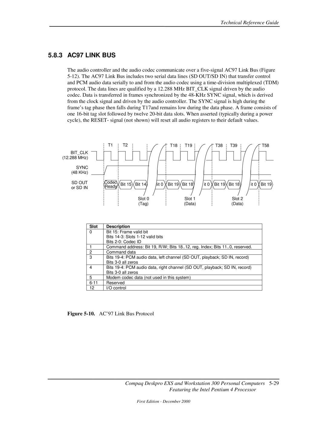
Slot Description
3 AC97 Link BUS
Sync
SD OUT
Audio Codec
Audio Control
Audio Configuration
AC’97 Audio Controller PCI Configuration Registers
Audio Programming
Audio Specifications
Audio Subsystem Specifications
Paramemter Measurement
AOL Events
Network Support
PCI VER .2 Support
ALERT-ON-LAN Support
Input/Output Interfaces
Remote System Alert Support
AOL/SOS
SOS
Remote System Alert Events
Power Supply ASSEMBLY/CONTROL
Distribution
AUX
Power Supply Assembly
Watt Power Supply Assembly Specifications P/N
Range Min. Current Max Surge
System Board LED Indications
Power Control
Power Button
System State Pressed Power Button Results
Wake-On-LAN
Power LED Indications
Power Management Event
Wake Up Events
RTN
Power Distribution
1 3.3/5/12 VDC Distribution
Conn Pin
VID1 VID2 VID3 VID4
LOW Voltage PRODUCTION/DISTRIBUTION
VID0
AGP PWR Rimm
IDE I/F CD-ROM
Signal Distribution
System
Board
Power Button/LED Header P5
CD ROM Audio Header P7
AOL/SOS Header P12
Bios ROM
Bios ROM
Num Lock Cap Lock Scroll Lock
Boot Block Codes
ROM Flashing
Upgrading
\Flashi.exe ImageFilename BackgroundColor ForegroundColor
Changeable Splash Screen
Boot Functions
Boot Device Order
Network Boot F12 Support
Visual Audible Meaning
Memory Detection and Configuration
Boot Error Codes
Boot Error Codes
Setup Utility
Setup Utility Functions
Heading Option Description
Multisector Transfers IDE ATA devices only
Translation Mode IDE disks only
Removable Media Boot
Translation Parameters IDE Disks only
See the Desktop Management Guide for more
CTRL+ALT+DEL
Setup Utility Functions
Setup Utility Functions
Setup Utility Functions
Function Mode
Client Management Functions
Client Management Functions INT15
ECX
Input EAX
Output
EBX
System System ID ROM Family PnP ID
Temperature Status
System ID and ROM Type
Edid Retrieve
Smart Hard Drive detects imminent failure
Drive Fault Prediction
PnP Bios Functions
PNP Support
Smbios
Independent PM Support
Power Management Functions
System Timer
IDE Hard Drive Timer
Suspend
Going to Sleep in Independent PM
System Standby
IDE Hard Drive Standby
APM 1.2 Support
Acpi Support
APM Bios Function Description
APM Bios Functions
Staying Awake in APM
Going to Sleep in APM
System/Hard Drive Standby
System Suspend
USB Legacy Support
Waking Up in APM
This page is intentionally blank
Beep/Keyboard LED Codes
Error Messages and Codes
BEEP/KEYBOARD LED Codes
Table A-1
Table A-2
POWER-ON Self Test Post Messages
Power-On Self Test Post Messages
Error Message Probable Cause
Message Probable Cause
System Error Messages
System Error Messages
Table A-3
Table A-5
Memory Error Messages
Keyboard Error Messages
Table A-4
Table A-7
Printer Error Messages
Video Graphics Error Messages
Table A-6
Table A-9
Diskette Drive Error Messages
Serial Interface Error Messages
Table A-8
Table A-10
Modem Communications Error Messages
Table A-12
System Status Error Messages
Hard Drive Error Messages
Table A-11
Table A-14
Table A-13
Audio Error Messages
17 DVD/CD-ROM Error Messages
Network Interface Error Messages
Table A-19
Scsi Interface Error Messages 65xx-xx, 66xx-xx
Pointing Device Interface Error Messages
Table A-18
12Compaq Personal Computers
Ascii Character Set
Dec Hex Symbol
Ascii Character SET
Table B-1
Appendix B Ascii Character Set
Appendix C Keyboard
Keyboard
Keystroke Processing
Parameter Minimum Nominal Maximum
1 PS/2-TYPE Keyboard Transmissions
USB-TYPE Keyboard Transmissions
Standard Enhanced Keyboards
Keyboard Layouts
Figure C-6.National Windows 102W-Key Keyboard Key Positions
Windows Enhanced Keyboards
Figure C-8.8-Button Easy Access Keyboard Layout
Easy Access Keyboards
Special Single-Keystroke Functions
Keys
Windows Keystrokes
Multi-Keystroke Functions
Button # Description Default Function
Easy Access Keystrokes
Table C-1
Keyboard Commands
Keyboard-to-System Commands
Scan Codes
Key Make / Break Codes Hex Pos Mode
Table C-2
Keyboard Scan Codes
Key Make / Break Codes Hex Pos
Table C-2. Keyboard Scan Codes
2B/AB
7E/FE
Key
Figure C-9.PS/2 Keyboard Cable Connector Male
Connectors
Sgram Nvidia TNT2
COMPAQ/NVIDIA TNT2 PRO AGP Graphics Card
RAM DAC
Bios ROM
Functional Description
2D/VGA
Nvidia TNT2 Pro Graphics Display Modes
Resolution Bits per pixel Color Depth
Display Modes
Table D-1
Table D-2
Power Management and Consumption
Monitor Power Management Conditions
Software Support Information
SDA
Monitor Connector
DB-15 Monitor Connector Pinout
Table D-3
6Compaq Personal Computers
Sdram Nvidia
Appendix E Compaq/NVIDIA GeForce2 GTS AGP Graphics Card
Appendix E Compaq/NVIDIA GeForce2 GTS AGP Graphics Card
Nvidia GeForce2 GTS Graphics Display Modes
Table E-1
Table E-2
Table E-3
Video Feature Connector
Video In Connector Pinout
Table E-4
Appendix F Compaq/Lucent V.90 56K PCI Modem
COMPAQ/LUCENT V.90 56K PCI Modem
DSP DAA
Table F-1
Operating Parameters
Uart Transfer Rates
Transmission Modes
Programming
Connector
APM Environment
Acpi Environment
Appendix G COMPAQ/ELSA Gloria
Appendix G Compaq/ELSA GLoria II AGP Graphics Card
Elsa GLoria II Graphics Display Modes
Table G-1
Table G-2
Table G-3
Table G-4
RAM MGA
Appendix G Compaq/Matrox Millennium G450 AGP Graphics Card
MB Sdram
Ramdac
Matrox Millennium G450 Graphics Display Modes
Table H-1
Table H-2
Table H-3
Video Feature Connector
Network Interface Controller Adapters
TX/RX PHY
WOL Bios
Controller Type Featured on
VDC
Wake UP Functions
AOL Function
Ipsec Function
Power Management Support
Control Registers
Configuration
Adapter Programming
Control
DES/3DES, Hmac SHA-1, MD5
Network Connector
Adapter Specifications
Adapter Specifications
8Compaq Personal Computers
Sdram Nvidia NV11GL
COMPAQ/NVIDIA QUADRO2 MXR AGP Graphics Card
RAM DAC Sdram
Nvidia Quadro2 MXR Graphics Display Modes
Table J-1
Table J-2
Table F-3
6Compaq Personal Computers
AOL/SOS LED
Compaq PCI 10/100 Ethernet Adapter
GND VDC
SMB CS
TX/RX
AOL Function
RSA Function
Power Management Support
Figure K-4.AOL/SOS Connector 7-pin Header
2 AOL/SOS Connector
WOL Connector
Smbus Connector
Table K-1
Appendix L Compaq/Adaptec Scsi Host Adapter
COMPAQ/ADAPTEC 29160N Scsi Host Adapter
PCI Scsi
Table L-2
Scsi Adapter Programming Scsi Adapter Configuration
Scsi Adapter Control
Table L-1
Table L-3
Scsi Connectors
External 50-PIN Ultra Scsi Connector
External Ultra Scsi Connector Pinout
Internal 50-PIN Ultra Scsi Connector
Internal 50-Pin Ultra Scsi Connector Pinout
Table L-4
Internal 68-PIN ULTRA160 Scsi Connector
Ultra160 Scsi Connector Pinout
Table L-5
Dimm support
Index
Ipsec
Specifications
Electrical
Environmental
This page is intentionally blank