Keyboard
In idle state the MCU and radio go to sleep to save power, and the keyboard application remains waiting for input from the keys or Bind button. The timer is turned off to conserve power. This state is maintained indefinitely until a keystroke or a button press occurs.
The battery level is reported by the keyboard application when it detects a keystroke after it has been in an idle state for 8 seconds.
In the active state the keyboard attempts to deliver a packet for the amount of time designated in KEYBOARD_TX_TIMEOUT. The keyboard application is also responsible for detecting the Bind but- ton press and then calling the bind function in the protocol module.
The keyboard application sends keyboard reports as frequently as events arrive, but not any faster than the time defined in the macro KEY_DOWN_DELAY_SAMPLE_PERIOD. Carefully set this time so that the report rate does not exceed that which the USB bus is capable of handling. Keep in mind that the report rate varies slightly due to drift of the internal oscillator used to keep track of time.
4.3.5.2Mfgtest Module
The RDK provides a
If MFG_TEST_CODE is defined and ENTER_BY_PIN is not defined, holding down the system sleep key and the Bind button while inserting the batteries into the keyboard enters the manufacturing test mode.
If MFG_TEST_CODE and ENTER_BY_PIN are both defined, connecting pin 4 and 5 on the ISP header with a shunt and then inserting the batteries into the keyboard enters the manufacturing test mode.
The only way to exit this mode is to cycle power.
4.3.5.3Battery Module
The battery monitor circuit is implemented using the Low Voltage Interrupt (LVI) on the LP radio. Fol- lowing is an explanation of the process to measure the battery voltage.
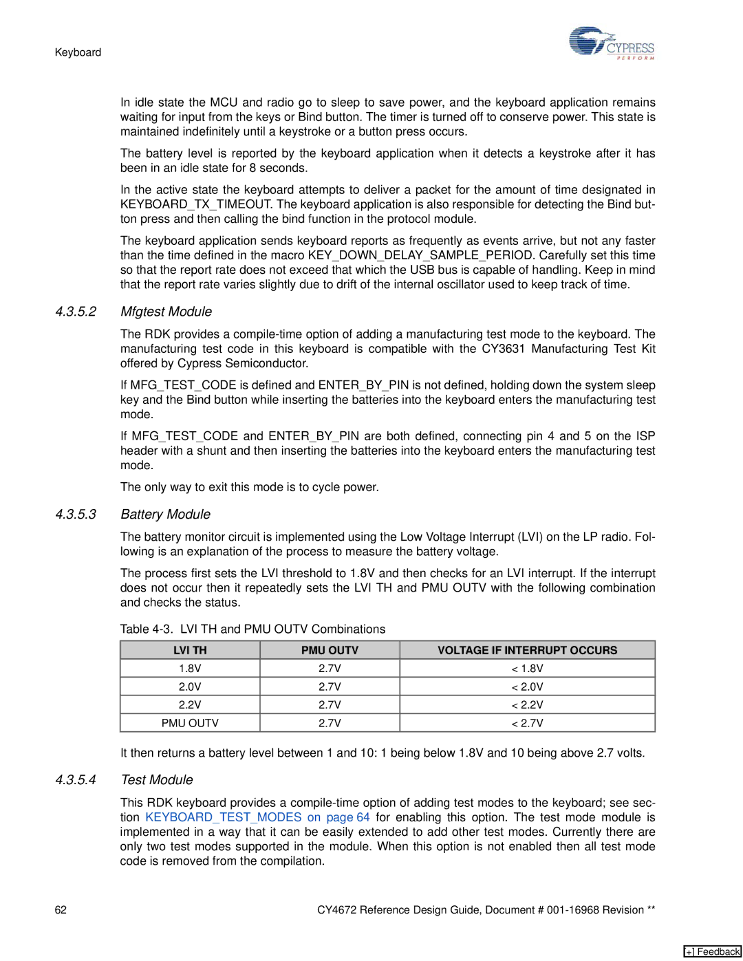
The process first sets the LVI threshold to 1.8V and then checks for an LVI interrupt. If the interrupt does not occur then it repeatedly sets the LVI TH and PMU OUTV with the following combination and checks the status.
Table
LVI TH | PMU OUTV | VOLTAGE IF INTERRUPT OCCURS |
1.8V | 2.7V | < 1.8V |
2.0V | 2.7V | < 2.0V |
2.2V | 2.7V | < 2.2V |
PMU OUTV | 2.7V | < 2.7V |
It then returns a battery level between 1 and 10: 1 being below 1.8V and 10 being above 2.7 volts.
4.3.5.4Test Module
This RDK keyboard provides a
62 | CY4672 Reference Design Guide, Document # |
[+] Feedback