System Board Layout
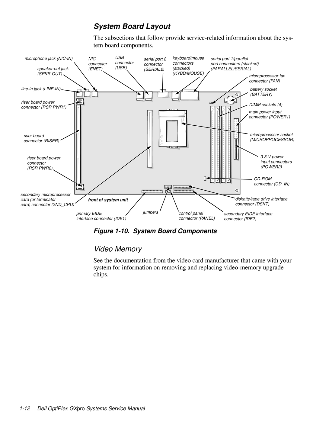
The subsections that follow provide
microphone jack
NIC | USB | serial port 2 | keyboard/mouse |
connector | connector | connector | connectors |
(ENET) | (USB) | (SERIAL2) | (stacked) |
|
|
| (KYBD/MOUSE) |
serial port 1/parallel
port connectors (stacked)
(PARALLEL/SERIAL)
microprocessor fan connector (FAN)
battery socket ![]() (BATTERY)
(BATTERY)
riser board power connector (RSR PWR1)
riser board connector (RISER)
riser board power connector (RSR PWR2)
DIMM sockets (4)
main power input |
connector (POWER1) |
microprocessor socket |
(MICROPROCESSOR) |
input connectors |
(POWER2) |
connector (CD_IN) |
secondary microprocessor card (or terminator
card) connector (2ND_CPU)
front of system unit |
|
| diskette/tape drive interface |
|
|
| connector (DSKT) |
primary EIDE | jumpers | control panel | secondary EIDE interface |
interface connector (IDE1) |
| connector (PANEL) | connector (IDE2) |
Figure 1-10. System Board Components
Video Memory
See the documentation from the video card manufacturer that came with your system for information on removing and replacing
