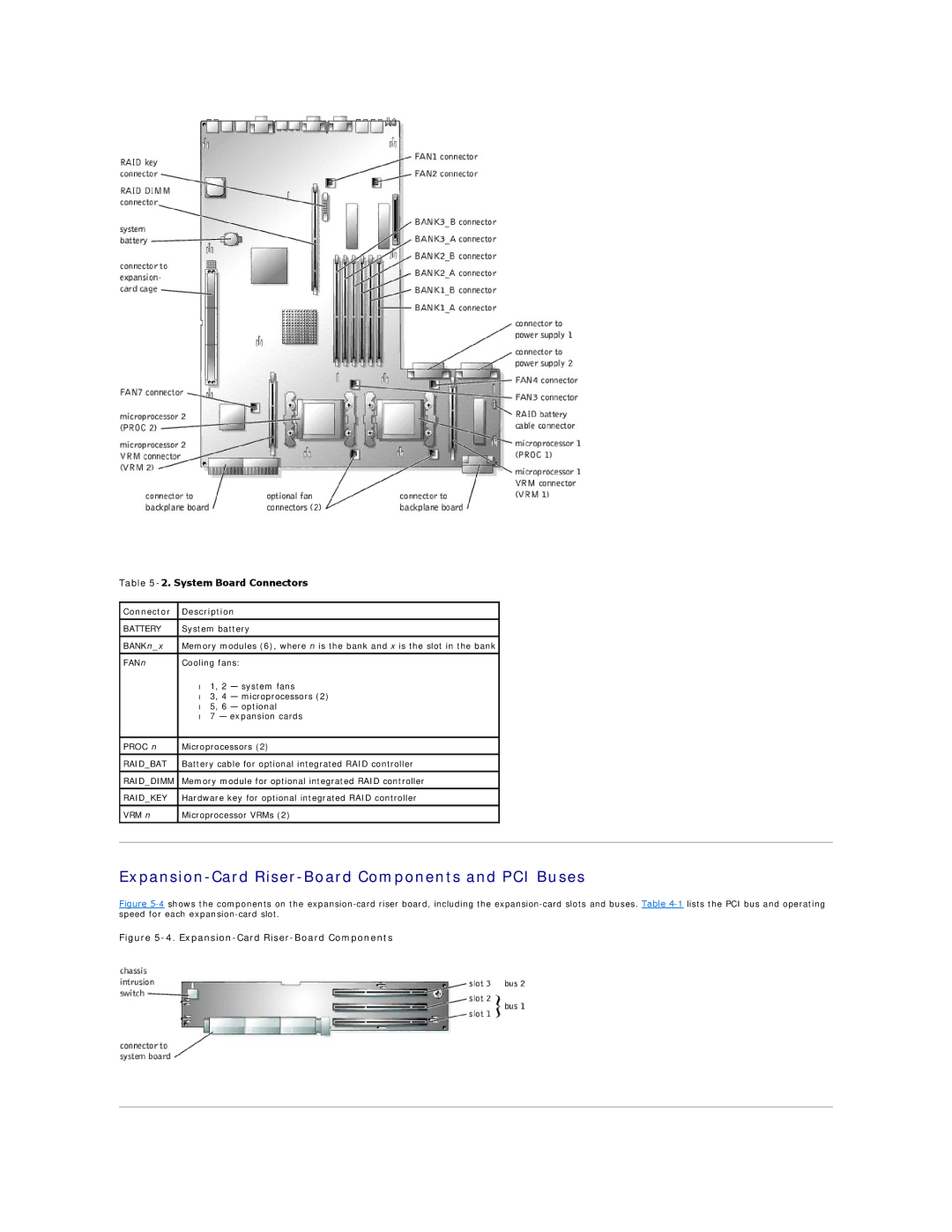
Table 5-2. System Board Connectors
Connector | Description |
| |
|
|
| |
BATTERY | System battery |
| |
|
|
| |
BANKn_x | Memory modules (6), where n is the bank and x is the slot in the bank |
| |
FANn | Cooling fans: |
| |
| • 1, 2 | — system fans |
|
| • 3, 4 | — microprocessors (2) |
|
| • 5, 6 | — optional |
|
| • 7 — expansion cards |
| |
|
|
| |
PROC n | Microprocessors (2) |
| |
|
|
| |
RAID_BAT | Battery cable for optional integrated RAID controller |
| |
|
|
| |
RAID_DIMM | Memory module for optional integrated RAID controller |
| |
|
|
| |
RAID_KEY | Hardware key for optional integrated RAID controller |
| |
|
|
| |
VRM n | Microprocessor VRMs (2) |
| |
|
|
|
|