Additional indicators are located behind the bezel. The
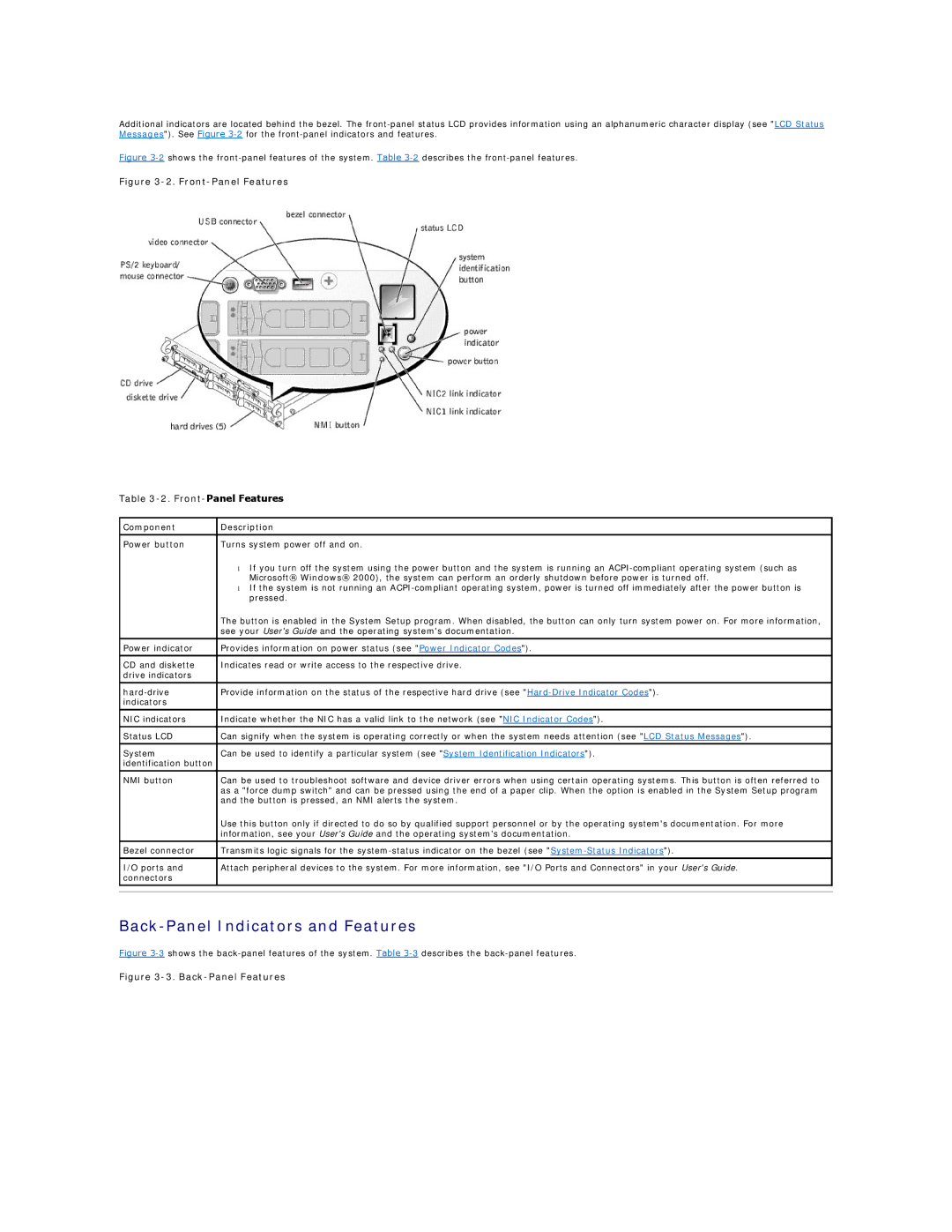
Figure 3-2 shows the front-panel features of the system. Table 3-2 describes the front-panel features.
Figure 3-2. Front-Panel Features
Table
Component | Description | |
|
| |
Power button | Turns system power off and on. | |
| • | If you turn off the system using the power button and the system is running an |
|
| Microsoft® Windows® 2000), the system can perform an orderly shutdown before power is turned off. |
| • | If the system is not running an |
|
| pressed. |
| The button is enabled in the System Setup program. When disabled, the button can only turn system power on. For more information, | |
| see your User's Guide and the operating system's documentation. | |
|
| |
Power indicator | Provides information on power status (see "Power Indicator Codes"). | |
|
| |
CD and diskette | Indicates read or write access to the respective drive. | |
drive indicators |
|
|
|
| |
Provide information on the status of the respective hard drive (see | ||
indicators |
|
|
|
| |
NIC indicators | Indicate whether the NIC has a valid link to the network (see "NIC Indicator Codes"). | |
|
| |
Status LCD | Can signify when the system is operating correctly or when the system needs attention (see "LCD Status Messages"). | |
|
| |
System | Can be used to identify a particular system (see "System Identification Indicators"). | |
identification button |
|
|
|
| |
NMI button | Can be used to troubleshoot software and device driver errors when using certain operating systems. This button is often referred to | |
| as a "force dump switch" and can be pressed using the end of a paper clip. When the option is enabled in the System Setup program | |
| and the button is pressed, an NMI alerts the system. | |
| Use this button only if directed to do so by qualified support personnel or by the operating system's documentation. For more | |
| information, see your User's Guide and the operating system's documentation. | |
Bezel connector | Transmits logic signals for the | |
|
| |
I/O ports and | Attach peripheral devices to the system. For more information, see "I/O Ports and Connectors" in your User's Guide. | |
connectors |
|
|
|
|
|
|
|
|