Replacing the Control Panel
CAUTION: Before you perform this procedure, read the safety instructions in your System Information document.
CAUTION: See "Protecting Against Electrostatic Discharge" in the safety instructions in your System Information document.
1.Lower the
2.Connect the
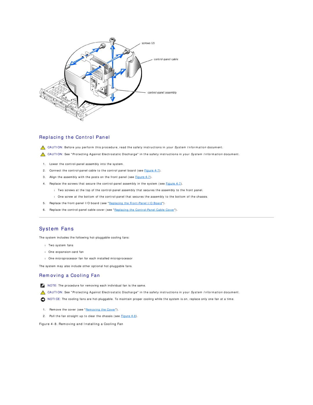
3.Align the assembly with the posts on the front panel (see Figure
4.Replace the screws that secure the
•Two screws at the top of the
•One screw at the bottom of the
5.Replace the
6.Replace the
System Fans
The system includes the following
•Two system fans
•One
•One microprocessor fan for each installed microprocessor
The system may also include other optional
Removing a Cooling Fan
NOTE: The procedure for removing each individual fan is the same.
CAUTION: See "Protecting Against Electrostatic Discharge" in the safety instructions in your System Information document.
NOTICE: The cooling fans are
1.Remove the cover (see "Removing the Cover").
2.Pull the fan straight up to clear the chassis (see Figure