Perc 3 User’s Guide
July 5C229
General
Safety Instructions
When Using Your Computer
When Working Inside Your Computer
Protecting Against Electrostatic Discharge
Ergonomic Computing Habits Battery Disposal
W . d e l l . c o m s u p p o r t . d e l l . c o m
Contents
Perc 3/SC Fault Tolerance Features
Configuration on Disk Configuration
Operating System Software Drivers
Perc 3/SC Bios
Hardware Architecture Features Array Performance Features
Configuring Scsi Physical Drives
Perc 3/QC Features
102
Planning the Array Configuration
103
131
118
119
120
136
135
150
173
Enabling and Disabling the Cluster Mode 185
163
167
197
190
Designating Drives as Hot Spares 195
196
Glossary Index
Figures
Figures
Tables
Perc 3/QC Specifications
182
Bios Boot Error Messages
C T I O N
E r v i e w
Perc 3 Overview
Perc 3 Features
Scsi Channels
Scsi Connectors
Maximum Cable Length for Scsi Standards
Single-Ended and LVD Scsi Buses
Scsi Bus Widths and Maximum Throughput
Scsi Standard Scsi Bus Width Scsi Throughput
Operating System Support
Over view
Introduction to RAID
RAID Definition
Perc 3 Host-Based RAID Solution
Logical Drive
Components and Features
Fault Tolerance
Physical Array
Disk Striping
Consistency Check
Stripe Size
Stripe Width
G u r e 2 1 . E x a m pl e o f D i s k S t r i p i n g
G u r e 2 2 . E xa m pl e o f D i s k M i r r or i n g
Disk Mirroring
G u r e 2 3 . E x a m pl e o f D i s k S p an n i n g
Disk Spanning
Ta b l e 2 2 . Ty pe s o f Par i t y
Describes how to configure RAID 10 and RAID 50 by spanning
Spanning for RAID 10 or RAID
Parity
G u r e 2 4 . E x a m pl e o f Par i t y
Hot Spares
Global Hot Spare
Disk Rebuilds
Dedicated Hot Spare
Scsi drive states are listed in Table
Hot Swap
Scsi Drive States
Rebuild Rate
Ta b l e 2 3 . S C S I D r i v e S t a t e s
Logical Drive States
Enclosure Management
Logical drive states are listed in Table
RAID Levels
Tab l e 3 1 . R a I D Le v el s
Perc 3 also supports independent drives configured as RAID
Overview
Selecting a RAID Level
Large files. Any environment that does not require
Fault tolerance
Does not provide fault tolerance. All data lost if any
RAID 0 provides high data throughput, especially for
G u r e 3 1 . R a I D 0 a r r a y
Displays an example of a RAID 0 array
Capacity
Environment that requires fault tolerance but small
Ideal for any application that requires fault tolerance
Use RAID 1 for small databases or any other
G u r e 3 2 . R a I D 1 a r r a y
Large files. Use RAID 5 for transaction processing
Office automation and online customer service that
Requires fault tolerance. Use for any application that
RAID 5 provides high data throughput, especially for
G u r e 3 3 . R a I D 5 a r r a y
Displays an example of a RAID 5 array
Redundancy of mirrored arrays and that also needs
Any environment that requires a higher degree of fault
2n, where n is greater than 1. The maximum number
RAID 10 works best for data storage that needs 100%
G u r e 3 4 . R a I D 1 0 a r r a y
RAID 50 provides high data throughput, data
RAID 50 works best when used with data that requires
High reliability, high request rates, and high data
Transfer and medium to large capacity
G u r e 3 5 . R a I D 5 0 a r r a y
Displays an example of a RAID 50 array
Perc 3/SC Features
Ta b l e 4 1 . C o nf i g u r a t i o n Fe at u r e s
Configuration Features
Specification Feature
Hardware Requirements
Smart Technology
Configuration on Disk Configuration
Ta b l e 4 1 . C on f i g u r a t i o n Fe at ur e s
Perc 3/SC array performance features are shown in Table
Hardware Architecture Features
Array Performance Features
Perc 3/SC hardware architecture features are shown in Table
Perc 3/SC software utilities are shown in Table
Perc 3/SC Fault Tolerance Features
Perc 3/SC fault tolerance features are shown in Table
Software Utilities
Operating System Software Drivers
Perc 3/SC Specifications
Perc 3/SC specifications are shown in Table
Ta b l e 4 7 . P E R C 3 / S C Specification s
Cache Memory
PCI Bridge/CPU
Scsi Termination
Onboard Speaker
Serial Port
Scsi Bus
RAID Management
Perc 3 Bios Configuration Utility
Feature Description
Scsi Firmware
Dell Manager
WebBIOS Configuration Utility
Dell OpenManage Array Manager
Perc 3/DC and Perc 3/DCL Features
MB Dimm Perc 3/DC
Ta b l e 5 1 . C o nf i g u r a t i o n Fe at u r e s
Configuration on Disk
Fe a t u r es
Ta b l e 5 5 . Fa u l t To l e r a n ce Fe at u r e s
Fault Tolerance Features
Lists the fault tolerance features
Ta b l e 5 4 . a r r a y Pe r f o r m a nc e Fe at u r e s
Ta b l e 5 6 . S o f t w a r e U t i l i t i e s
Perc 3/DC and Perc 3/DCL Specifications
Lists the Perc 3/DC and Perc 3/DCL specifications
Lists the software utilities
PCI Bridge/CPU
Perc 3/DC and Perc 3/DCL Bios
Ta b l e 5 8 . S C S I F i r mw ar e
RAID Management
Perc 3/QC Features
Ta b l e 6 1 . C o n f i g u r at i on Fe a t u r e s
Lists the Perc 3/QC configuration features
Smart Technology
Ta b l e 6 4 . a r r a y Pe r f o r m a n ce Fe at u r e s
Lists the Perc 3/QC hardware architecture features
Lists the array performance features
S k Fe a t u r es
Ta b l e 6 5 . Fa u l t To l e r a n ce Fe at u r e s
Fault tolerance features are listed in Table
Software utilities are listed in Table
Ta b l e 6 4 . a r r a y Pe r f o r m a nc e Fe at u r e s
Ta b l e 6 7 . P E R C 3 / Q C S pe c i f i c a t i o n s
Perc 3/QC Specifications
Perc 3/QC specifications are listed in Table
Ta b l e 6 6 . S o f t w a r e U t i l i t i e s
Ta b l e 6 7 . P E R C 3 / Q C Pe c i f i c a t i o n s
Perc 3/QC Bios
Ta b l e 6 8 . S C S I F i r mw ar e
Dell Manager
Configuring Perc
Scsi Channel
Configuring Scsi Physical Drives
Current Configuration
Device Description
Scsi ID
Scsi ID
Logical
Logical Drive Configuration
LD2 LD3 LD4 LD5 LD6 LD7 LD8 LD9
Ta b l e 7 6 . P h y s i c al D ev i c e L a y o ut
Physical Device Layout
Channel
W . d e l l . c o m s u p p o r t . d e l l . c o m
Ta b l e 7 6 . P h y s i c al D ev i c e L a y o ut
Configuring Arrays
Creating Logical Drives
Configuration Strategies
Arranging Arrays
Creating Hot Spares
Description Drives Capacity Level Required
Fault Tolerance Protection
Maximizing Capacity
Maximizing Drive Availability
Maximizing Drive Performance
Assigning RAID Levels
Data Access Requirements
Configuring Logical Drives
Optimizing Data Storage
Array Functions
Planning the Array Configuration
Question Answer
Using the Array Configuration Planner
Overview
Random Array Deletion
Ta b l e 7 1
100
Configuration Module
Perc 3/SC Hardware Installation
Optional Equipment
Requirements
Perc 3/SC Card Layout
Installation Steps
G u r e 8 1 . P E R C 3 / S C C a r d L a yo u t
104
Power Down
License agreement Perc 3 configuration utilities diskette
Unpack
Set Jumpers
J1 Termination Enable
Tab l e 8 1 . P E R C 3 / S C J u mp e r s
N o u t
J9 I2C Interface Connector
J5 Serial Port
Ta b l e 8 3 . J9
Ta b l e 8 5 . J 8 H a r d D i s k L E D
J10 Term Power
J8 Hard Disk LED
J15 Rubi Slot Interrupt Steering
108
Set Scsi Termination
J16, J17 Rubi Slot Interrupt Steering
G u r e 8 2 . E xa m pl e o f S C S I Te r m i n at i on
109
Scsi Termination
Selecting a Terminator
Terminating Internal Scsi Disk Arrays
ID2
G u r e 8 4 . P C I S l o t s o n M o t h e r b o ar d
Install Perc 3/SC
111
112
113
Connect Scsi Cables
Connect Scsi Devices
G u r e 8 6 . C o n n e ct i n g S C S I C a b l e s
Cable Suggestions
Set Target IDs
114
115
Power On Host System
Ta b l e 8 Tar g et
Priority Highest Lowest
Install Operating System Software Drivers
Run Perc 3 Bios Configuration Utility or WebBIOS Utility
116
Perc 3/DC or Perc 3/DCL Hardware Installation
Perc 3/DC or Perc 3/DCL Hardware Installation
G u r e 9 1 . P E R C 3 / D C C a r d L a y ou t
Perc 3/DC Card Layout
G u r e 9 2 . P E R C 3 / D C L C ar d L ay o u t
Perc 3/DCL Card Layout
Ta b l e 9 1 . J u mp e r S e t t i n g s
Unpack the Perc 3/DC or Perc 3/DCL
121
Jumper
J2, and J3 Termination Enable
J9 Onboard Bios Enable
J9 Setting Onboard Bios Status
J11 Serial Port
J10 Nvram Clear
J13 Dirty Cache LED
Ta b l e 9 7 . J1 4 S C S I a c t i v i t y P i n o u t
J16 and J18 Termpwr Enable
J14 Scsi Activity LED
Tab l e 9 6 . J 1 3 D i r t y C ac h e L E D P i n ou t
125
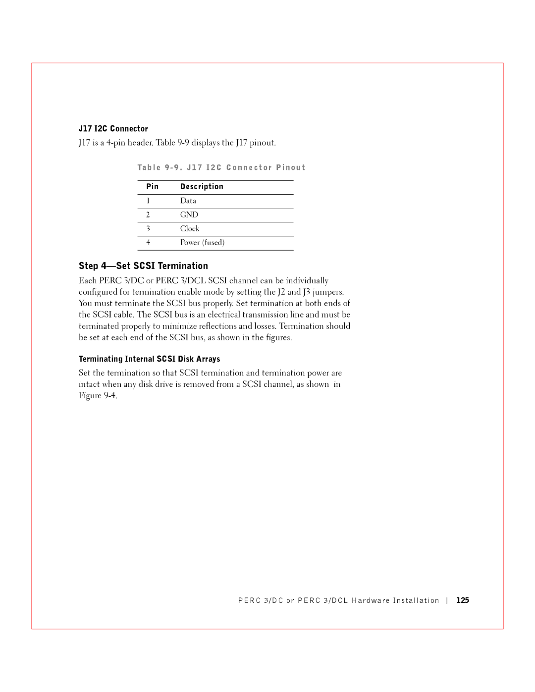
J17 I2C Connector
J17 is a 4-pin header. -9 displays the J17 pinout
Ta b l e 9 9 . J 1 7 I 2 C C o n n e ct or P i n o u t
126
Install the Perc 3/DC or Perc 3/DCL Controller
127
128
Select and Set Target IDs for Scsi Devices
129
130
Proceed to the Windows Device Manager
Install Operating System Software Driver
Using Driver 5.22.1 or 5.22.2 and Firmware 161J or 161N
Using Driver 5.30 and Firmware
132
C T I O N 1
Perc 3/QC Hardware Installation
134
G u r e 1 0 1 . P E R C 3 / Q C C a r d L a yo u t
Perc 3/QC Card Layout
Unpack the Perc 3/QC Controller
License agreement Perc 3/QC Configuration Utilities diskette
137
Ta b l e 1 0 1 . P E R C 3 / Q C J u m p er S et t i n g s
138
J2, J3, J5, and J7 Termination Enable
J9, J10, J11, and J12 Termpwr Enable
Jumper Term Settings Power Channel
J14 Serial Port
J19 Onboard Bios Enable
J17 Dirty Cache LED
140
J23 External Battery
J19 Setting Onboard Bios Status
Tab l e
141
G u r e 1 0 3 . E x a mp l e o f Te r m i n at i o n
142
G u r e 1 0 5 . P C I S l o t s o n M o t h e r b o ar d
Install Perc 3/QC
143
144
145
G u r e 1 0 7 . C o n n e ct i n g S C S I C a b l e s
146
147
Install Operating System Driver
Perc 3/QC Hardware Installation
Perc 3 Bios Configuration Utility
Starting the Perc 3 Bios Configuration Utility
Configuration On Disk
Select Configure Menu-View/Add Configuration
Option Description
Bios Configuration Utility Menu Options
152
Configure Menu
Ta b l e 1 1 3 . a d ap t er M en u O p t i on s
Initialize Menu
Objects Menu
Adapter
154
Ta b l e 1 1 Log i c a l D r i v e M en u O p t i o ns
Cluster Mode and the Initiator ID
Logical Drive
Virtual Sizing
Physical Drive
Select Enabled to enable Virtual Sizing
156
Menu Item Explanation
Battery Information
Channel
Ta b l e 1 1 6 . S C S I C h an n e l M e nu O pt i o n s
Rebuild Menu
Reset Battery Charge Counter
Select Reset Battery Charge Counter
Format Menu
Check Consistency Menu
Configuring Arrays and Logical Drives
Easy Configuration
Choosing the Configuration Method
New Configuration
Displays the default settings for Perc 3/QC and Perc 3/DC
View/Add Configuration
Perc 3/QC and Perc 3/DC Default Settings
Perc 3/SC and Perc 3/DCL Default Settings
Press F4
Reserved Disk Space during Configuration
Using the Objects-Physical Drive menu
Designating Drives as Hot Spares
Using Easy Configuration
164
165
Set the Stripe Size from the Advanced Menu
Set the Read Policy from the Advanced Menu
Set the Write Policy from the Advanced Menu
166
Choose Configure-New Configuration from the Management Menu
Using New Configuration
168
169
170
171
Set the Stripe Size
Set the Write Policy
Set the Read Policy
172
Set the Cache Policy
Using View/Add Configuration
174
175
176
177
Batch Initialization
Initializing Logical Drives
Individual Initialization
Deleting Logical Drives Random Array Deletion
Select Objects-Physical Drives from the Management Menu
Media Errors
Formatting Physical Drives
Formatting Drives
Individual Formatting
Physical Drive action menu for a physical drive
Batch Formatting
Select Format from the Management Menu
Choose Rebuild from the Management Menu
Manual Rebuild Batch Mode
Rebuilding Failed Disk Drives
Manual Rebuild Rebuilding an Individual Drive
Select Configure-Easy Configuration
Using a Pre-loaded Scsi Drive As-is
Setting Hardware Termination
Exiting the Perc 3 Bios Configuration Utility
Enabling and Disabling the Cluster Mode
Cluster Mode
Clustering
186
Select Objects-Adapter-Cluster Mode Select Enable or Disable
Dell Manager
First Dell Manager screen displays the Management Menu
Starting Dell Manager
Type this
Ta b l e 1 2 2 . M a na g e me n t M e n u O p t i o n s
Using Dell Manager in Red Hat Linux GUI Mode
Management Menu Options
Displays the options for the Dell Manager Management Menu
Ta b l e 1 2 3 . a d ap t er M en u O p t i on s
Dell Manager Menu Options
191
Logical Drive Settings
Parameter Setting
Ta b l e 1 2 3 . a d ap t er Me n u O p t i on s
192
Physical Drive Menu
Displays the options in the physical drive menu
Tab l e 1 2
Ta b l e 1 2 8 . B a t t er y B a ck u p M e n u I t e m s
Battery Backup
Scsi Channel
Ta b l e 1 2 7 . S C S I C h an n e l O p t i on s
194
Reconstruct Menu
Parameters
Initializing Logical Drives
Select Objects-Logical Drive
Perform the following steps to initialize one logical drive
Select Physical Drive-Objects
Choose Objects-Logical Drive. The logical drives display
Select Objects-Physical Drive on the Management Menu
Choose Format on the Management Menu
Ta b l e 1 2 Re b u i l d Typ e s
Perform the following steps to rebuild one drive
Perform the following steps to rebuild more than one drive
Exiting Dell Manager
Tr o u b l e s h o o t i n g
Problem Suggested Solution
Ta b l e 1 3 2 . B I O S B o ot Error M e s s a ge s
Bios Boot Error Messages
Message Problem Suggested Solution
206
View/Add Configuration
207
Explains the other Bios error messages that can display
Other Bios Error Messages
Ta b l e 1 3 3 . O t h er B I O S Error Me s s a g e s
Topic Information
Other Potential Problems
Describes other items that might cause problems
Ta b l e 1 3 4 . O t h e r Po t e n t i a l P r o b l e ms
Ta b l e 1 3 5 . a u di bl e Wa r n i n g s
Audible Warnings
Tone Pattern Meaning Examples
Appendix a Scsi Cables and Connectors
Appendix a Scsi Cables and Connectors
Appendix B Warranties and Return Policy
214
One-Year Limited Warranty U.S. Only
215
216
Two-Year Limited Warranty U.S. Only
217
Limited Warranty Coverage During Year One
218
Limited Warranty Coverage During Year Two
219
General Provisions
220
Three-Year Limited Warranty U.S. Only
221
Limited Warranty Coverage During Years Two and Three
222
223
Four-Year Limited Warranty U.S. Only
224
Limited Warranty Coverage During Years Two, Three, and Four
225
226
One-Year Limited Warranty Canada Only
227
228
Two-Year Limited Warranty Canada Only
229
230
231
Three-Year Limited Warranty Canada Only
232
233
234
Total Satisfaction Return Policy U.S. Only
235
Guarantee
Exclusions
Making a Claim
Carrera 7 #115-33 Oficina Bogota, Colombia
Limitation and Statutory Rights
Dell World Trade LP
Dell Computer de Colombia Corporation
237
Glossary
238
239
240
241
242
243
244
245
Gl ossar y
247
D ex
248
249
250
Page
5C229 Rev. A04