CS24-TY, C1100 specifications
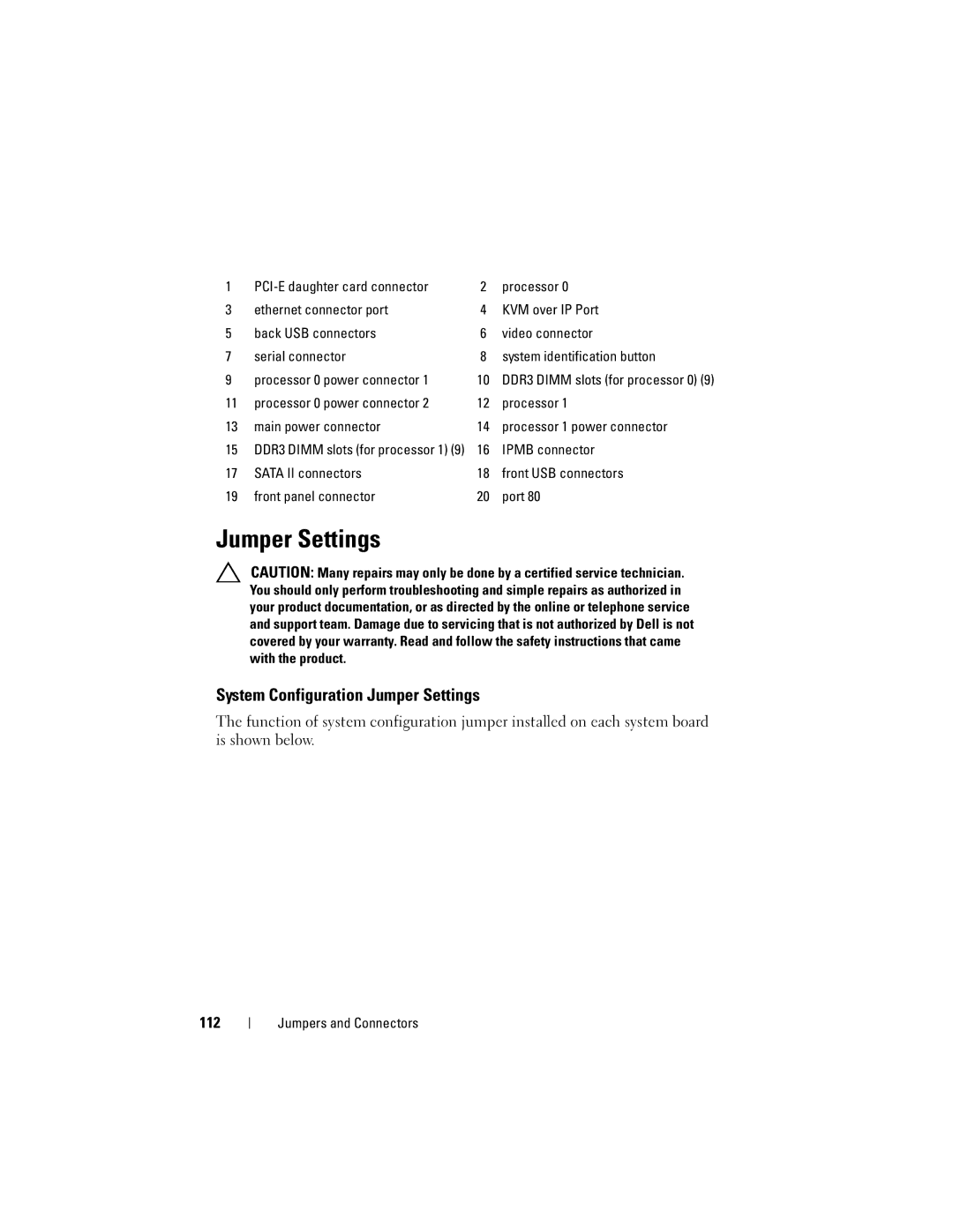
The Dell C1100 is a notable entry in the realm of high-density computing solutions, designed primarily for data centers and enterprise environments that require powerful performance in a compact form factor. As part of Dell's PowerEdge series, the C1100 is built to support a range of applications, from cloud computing to virtualization and big data analytics.One of the main features of the Dell C1100 is its highly modular architecture. This design facilitates easy upgrades and maintenance, allowing users to configure the system according to their specific needs. The C1100 can support a variety of server configurations, with options for multiple processor types including Intel Xeon processors, which provide enhanced performance for multi-threaded applications. This ensures that users can deploy the right resources for their workloads without being constrained by hardware limitations.
Additionally, the Dell C1100 stands out with its support for up to 96GB of DDR3 memory across six DIMM slots. This significant memory capacity enables the server to handle large datasets and perform complex computations, making it ideal for tasks such as data analysis and high-performance computing.
The storage capabilities of the C1100 are also noteworthy. The system supports multiple storage configurations, including direct-attached storage (DAS) options and the ability to integrate with SAN solutions. Users can configure the server with up to four 3.5-inch drive bays, allowing for a mix of SSD and HDD options tailored to performance and capacity needs. Moreover, the C1100 offers advanced RAID options to ensure data integrity and availability.
In terms of networking, the Dell C1100 provides flexible connectivity options. With multiple Ethernet ports, users can configure the network settings to meet their needs, whether deploying a single network interface or leveraging multiple interfaces for redundancy and enhanced bandwidth.
Another significant aspect of the Dell C1100 is its energy efficiency. The design prioritizes reduced power consumption, which is crucial for data centers looking to minimize operational costs. The server incorporates a range of energy-saving technologies, including advanced power management features that allow for optimized energy usage without sacrificing performance.
Overall, the Dell C1100 represents a compelling solution for organizations seeking a balance of performance, scalability, and efficiency. Its modular design, robust hardware capabilities, and energy-efficient features make it a valuable asset for data-driven businesses and IT departments aiming to maximize their return on investment. With a focus on versatility and performance, the C1100 is a strong contender in the high-density server market.
