Installing The Cooling Shroud
CAUTION: Many repairs may only be done by a certified service technician. You should only perform troubleshooting and simple repairs as authorized in your product documentation, or as directed by the online or telephone service and support team. Damage due to servicing that is not authorized by Dell is not covered by your warranty. Read and follow the safety instructions that came with the product.
NOTE: For proper seating of the cooling shroud in the chassis, ensure that the cables inside the system are routed through the cable routing latch.
1.Position the cooling shroud by aligning the
2.Lower the cooling shroud into the chassis until all edges are secured to the system board.
When firmly seated, the memory socket numbers marked on the cooling shroud align with the respective memory sockets.
3.Close the system.
4.Reconnect the system to the electrical outlet and turn the system on, including any attached peripherals.
System Memory
Your system supports DDR3 unbuffered ECC DIMMs. It supports DDR3 and DDR3L voltage specifications.
NOTE: MT/s indicates DIMM speed in MegaTransfers per second.
Memory bus operating frequency can be 1600 MT/s or 1333 MT/s, depending on:
•maximum frequency of the DIMMs
•maximum supported DIMM frequency of the processor
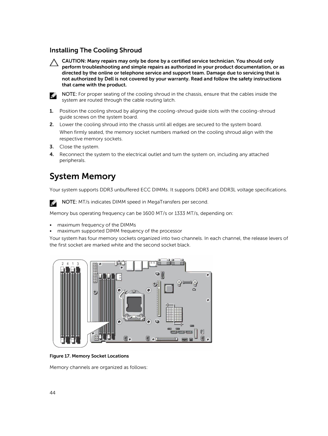
Your system has four memory sockets organized into two channels. In each channel, the release levers of the first socket are marked white and the second socket black.
Figure 17. Memory Socket Locations
Memory channels are organized as follows:
44