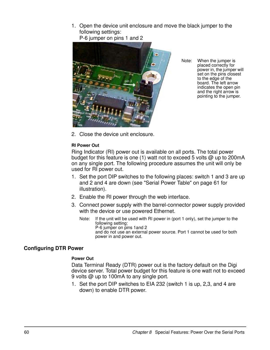
1.Open the device unit enclosure and move the black jumper to the following settings:
Note: When the jumper is placed correctly for power in, the jumper will set on the pins closest to the edge of the board. The left arrow indicates the open pin and the right arrow is pointing to the jumper.
2. Close the device unit enclosure.
RI Power Out
Ring Indicator (RI) power out is available on all ports. The total power budget for this feature is one (1) watt not to exceed 5 volts @ up to 200mA on any single port. The following procedure assumes the unit will only be used for RI power out.
1.Set the port DIP switches to the following places: switch 1 and 3 are up and 2 and 4 are down (see "Serial Power Table" on page 61 for illustration).
2.Enable the RI power through the web interface.
3.Connect power supply with the
Note: If the unit will be used with RI power in (port 1 only), set the jumper to the following setting:
and do not use an external power source. Port 1 cannot be used for both power in and power out.
Configuring DTR Power
Power Out
Data Terminal Ready (DTR) power out is the factory default on the Digi device server. Total power budget for this feature is one watt not to exceed 9 volts @ up to 100mA to any single port.
1.Set the port DIP switches to EIA 232 (switch 1 is up, 2,3, and 4 are down) to enable DTR power.
60 | Chapter 8 Special Features: Power Over the Serial Ports |