Always On / Dynamic ISDN AT Commands
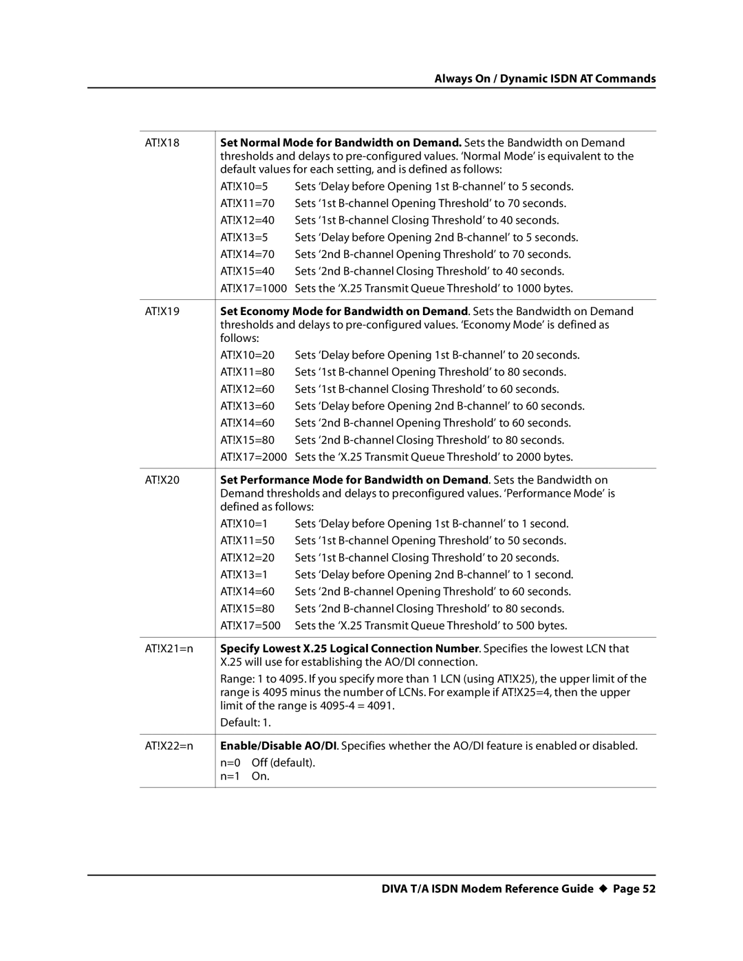
AT!X18 | Set Normal Mode for Bandwidth on Demand. Sets the Bandwidth on Demand | ||
| thresholds and delays to | ||
| default values for each setting, and is defined as follows: | ||
| AT!X10=5 | Sets ‘Delay before Opening 1st | |
| AT!X11=70 | Sets ‘1st | |
| AT!X12=40 | Sets ‘1st | |
| AT!X13=5 | Sets ‘Delay before Opening 2nd | |
| AT!X14=70 | Sets ‘2nd | |
| AT!X15=40 | Sets ‘2nd | |
| AT!X17=1000 | Sets the ‘X.25 Transmit Queue Threshold’ to 1000 bytes. | |
|
| ||
AT!X19 | Set Economy Mode for Bandwidth on Demand. Sets the Bandwidth on Demand | ||
| thresholds and delays to | ||
| follows: |
| |
| AT!X10=20 | Sets ‘Delay before Opening 1st | |
| AT!X11=80 | Sets ‘1st | |
| AT!X12=60 | Sets ‘1st | |
| AT!X13=60 | Sets ‘Delay before Opening 2nd | |
| AT!X14=60 | Sets ‘2nd | |
| AT!X15=80 | Sets ‘2nd | |
| AT!X17=2000 | Sets the ‘X.25 Transmit Queue Threshold’ to 2000 bytes. | |
|
| ||
AT!X20 | Set Performance Mode for Bandwidth on Demand. Sets the Bandwidth on | ||
| Demand thresholds and delays to preconfigured values. ‘Performance Mode’ is | ||
| defined as follows: | ||
| AT!X10=1 | Sets ‘Delay before Opening 1st | |
| AT!X11=50 | Sets ‘1st | |
| AT!X12=20 | Sets ‘1st | |
| AT!X13=1 | Sets ‘Delay before Opening 2nd | |
| AT!X14=60 | Sets ‘2nd | |
| AT!X15=80 | Sets ‘2nd | |
| AT!X17=500 | Sets the ‘X.25 Transmit Queue Threshold’ to 500 bytes. | |
|
| ||
AT!X21=n | Specify Lowest X.25 Logical Connection Number. Specifies the lowest LCN that | ||
| X.25 will use for establishing the AO/DI connection. | ||
| Range: 1 to 4095. If you specify more than 1 LCN (using AT!X25), the upper limit of the | ||
| range is 4095 minus the number of LCNs. For example if AT!X25=4, then the upper | ||
| limit of the range is | ||
| Default: 1. |
| |
|
| ||
AT!X22=n | Enable/Disable AO/DI. Specifies whether the AO/DI feature is enabled or disabled. | ||
| n=0 | Off (default). | |
| n=1 | On. |
|
|
|
|
|