300510EN specifications
The Emerson 300510EN is a remarkable product designed to meet the evolving needs of industrial automation. Known for its robust performance and advanced features, it has become an integral component in various industries, ensuring optimal efficiency and reliability in operations.At the core of the Emerson 300510EN is its high-performance processing capability. It is equipped with an advanced microprocessor that allows for rapid data processing and seamless integration with existing systems. This ensures real-time monitoring and control, enabling companies to make informed decisions quickly and effectively.
One of the standout features of the Emerson 300510EN is its user-friendly interface. The device incorporates a touchscreen display, providing operators with intuitive access to critical information. This simplifies navigation through various functions and settings, enhancing user experience and reducing the risk of errors during operation.
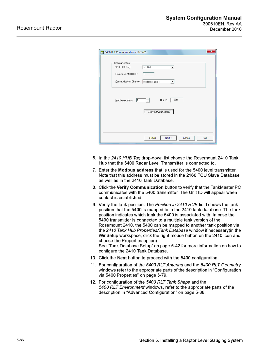
In terms of connectivity, the Emerson 300510EN supports multiple communication protocols, including MODBUS, Ethernet/IP, and Profibus. This versatility allows for seamless integration with a wide range of industrial equipment and systems, facilitating enhanced interoperability in complex automation environments. As industries increasingly adopt IoT technologies, the Emerson 300510EN remains adaptable, ensuring businesses can evolve without significant overhauls of their existing setups.
Reliability is another hallmark of the Emerson 300510EN. The device is designed to withstand harsh industrial environments, with robust casing and components that protect against dust, moisture, and temperature fluctuations. This durability minimizes the risks of downtime, ensuring that operations run smoothly.
The Emerson 300510EN also comes equipped with advanced diagnostic features. These built-in capabilities allow for proactive maintenance and troubleshooting, reducing unexpected failures and associated costs. By providing real-time diagnostics, operators can quickly identify issues and implement solutions before they escalate.
Overall, the Emerson 300510EN stands out as a highly effective solution for industrial automation needs. Its blend of advanced processing power, user-friendly design, versatile connectivity, reliability, and proactive diagnostics makes it an invaluable tool for businesses striving to enhance productivity and efficiency in an increasingly competitive marketplace.

