Raptor
System Configuration Manual
Page
Version
Page
Table of Contents
Table of Contents
Menu Guide
Device Handling Service Functions
TOC-4
Manual Overview
Menu Guide
Service Functions
Technical Documentation
Raptor System Overview
Raptor system architecture
Rosemount 5900S Radar Level Gauge
TankMaster HMI Software
Rosemount 2160 Field Communication Unit
Rosemount 2410 Tank Hub
Rosemount 5400 Radar Level Transmitter
Rosemount 2240S Multi-Input Temperature Transmitter
Rosemount 644 Temperature Transmitter
Rosemount 5300 Guided Wave Radar
Key Features
What is TANKMASTER?
Tankmaster Software Package
OPC Server with Browser Customized views
System Requirements
Installing the Tankmaster Software
Installed Software Modules
Installation Options
Installation Procedure
Wizards
Installing a Tank Level Gauging System Illegal Characters
Tank installation
Device installation
WinSetup Main Window
WinSetup workspace
Menus
Service , Tools , and Help
Toolbar
WinSetup Toolbar
Deselect the Status bar option
Status BAR
Workspace Viewing Tanks and Devices
Workspace
Icons
User Management
User Access Level Username Password
Logging On to TankMaster
From the ToolsAdministrative Tools menu choose User Manager
To Administrate User Accounts
New user account is added
Add Program see Customizing the Tools Menu in WinSetup on
To Set Required Access Levels
Choose the Protection Level... option
To Change Protection Level of Separate Windows
To Change Password
To Change Inactivity Timeout
Installing a Raptor Level Gauging System
Preferences
System Configuration Overview
Preparations Installation Procedure
Communication Protocol Setup
Raptor system installation procedure
Calibration
Installation and Configuration of Rosemount 2410 Tank Hub
Installation and Configuration of Field Devices
Device
Using the Device Installation Wizard
Slave Protocol
Communication Protocol Setup
Master Protocol Channel Configuration
Port
Modbus Master channel 1 is enabled
TRL2 Modbus Communication Setup
Slave Protocol Channel Configuration
Stop bits
Advanced Configuration
Tank mapping configuration
Protocols Protocol subfolder
Protocol Server Configuration
Measurement Units
Preferences
Ambient Air Temperature
Inventory
Server Preferences window select the Miscellaneous tab
Miscellaneous
Setting the Name Tag Prefixes
System Configuration Manual
System Configuration Manual
Visible Hidden
Select the Enable Tank Visibility function check box
Tank Visibility
Configuration
Field Device Installation Overview
Installing a Rosemount 2160 FCU
System Configuration Manual
How to change the Modbus address of the FCU
Fieldbus communication with a
Select Slave Type=2410
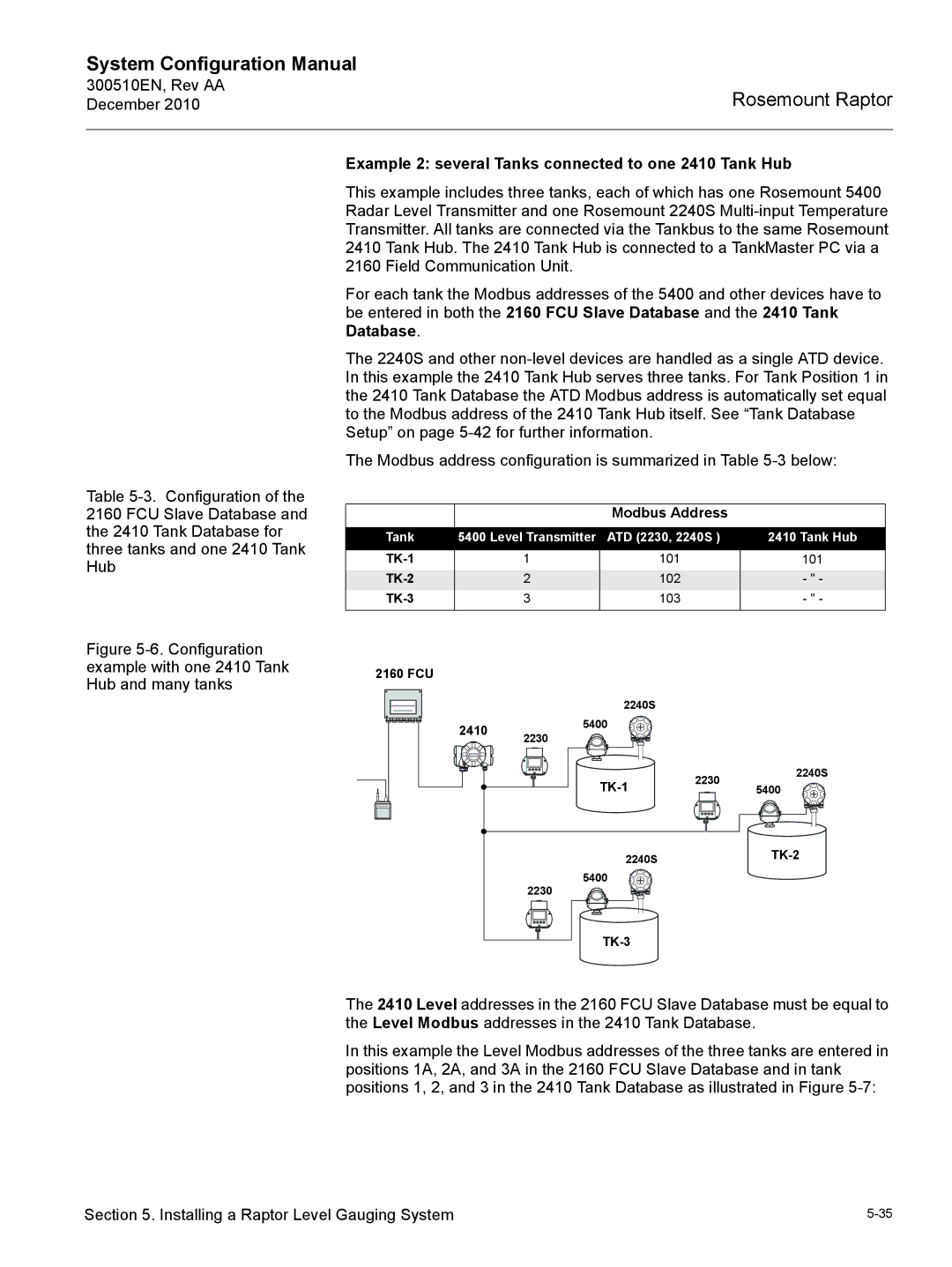
ATD Device Modbus Address 2410 Temp
See Examples of 2160 FCU Slave Database Configuration on
2160 Slave Database and the 2410 Tank Database
Level Gauge Modbus Address 2410 Level
Summary of FCU Slave Database entry fields
Example 1 single tank connected to one 2410 Tank Hub
Examples of 2160 FCU Slave Database Configuration
Tank Database TK-1 FCU Slave Database Tank Database TK-2
System Configuration Manual
ATD 2230, 2240S Tank Hub
Example 2 several Tanks connected to one 2410 Tank Hub
Tank Database FCU Slave Database
Summary of 2160 Installation and Configuration
Installation Wizard
Installing a Rosemount 2410 Tank HUB
Device Type
Communication Setup
How to change the Modbus address
Tank Database Setup
System Configuration Manual
Device Tag Setup
Variable Description
Local Display Setup
System Configuration Manual
Configuration Summary
Tank Hub Configuration window
Devices appear in the WinSetup workspace window
Summary of Tank Hub Installation and Configuration
System Configuration Manual
Installing a Rosemount 5900S Radar Level Gauge
5900S RLG Properties window appears
Configuration via the Properties Window
This field shows the tank position in the 2410 Tank Database
System Configuration Manual
5900S with Still-pipe Array Antenna
To configure a User Defined antenna advanced
5900S with Horn Antenna
5900S with Parabolic Antenna
Reference Distance G
5900S RLG Properties window select the Geometry tab
Tank Reference Height R
Enter the Calibration Distance
Minimum Level Distance C
Configure the Tank Database in the 2410 Tank Hub Properties
Installing a 5900S Using the Installation Wizard
Using the installation wizard
System Configuration Manual
System Configuration Manual
5900S RLG Properties window select the Tank Shape tab
Advanced Configuration
Tank Shape
5900S RLG Properties window select the Environment tab
Tank Environment
Rosemount 5900S Reference Manual Document no EN
Advanced Configuration Tab
Properties/Advanced Configuration window
Opening the Properties Window
Installing Auxiliary Tank Devices
System Configuration Manual
Communication Parameter Setup
22xx ATD window select the 2240S MTT Temperature Sensor tab
Temperature Sensor Configuration
System Configuration Manual
Average Temperature Calculation
System Configuration Manual
22xx ATD window, select the 2240S MTT Auxiliary Sensor tab
Auxiliary Sensor Configuration
Water Level Sensor
System Configuration Manual
Advanced Parameter Source Configuration
Configuration Temperature Transmitters
22xx ATD window, select the 2230 Graphical Field Display tab
7 2230 Graphical Field Display
System Configuration Manual
Installing a Rosemount
Configuration via 5400 Properties
System Configuration Manual
Still-pipes
Free Propagation
Tank Reference Height R
See the Rosemount 5400 Reference Manual
Installing a 5400 Using the Installation Wizard
Using the installation wizard
System Configuration Manual
System Configuration Manual
Advanced Configuration
See the Rosemount 5400 Reference Manual Document No
Installing a Rosemount
5300 GWR window appears
Configuration via 5300 Properties
System Configuration Manual
System Configuration Manual
See the Rosemount 5300 Reference Manual
Installing a 5300 Using the Installation Wizard
Using the installation wizard
System Configuration Manual
System Configuration Manual
Dielectric Constant/Dielectric Range
Measurement Mode
Rapid Level Change
100
Installing a Tank 5.11.1 Overview
See also Installing a New Tank on
Starting the Tank Installation Wizard
Installing a New Tank
300510EN, Rev AA December Assign devices to the current tank
Show 2160 FCU Slave Positions Advanced
Select the Advanced Parameter Source Configuration tab
22XX ATD/PARAMETER Source Window Tank Configuration Window
108
109
Summary
Select Devices
Summary of Tank Installation and Configuration
Tank Configuration
Tank Type
To Change Tank Configuration
To Uninstall a Tank
12. a new tank and 2410 Tank Hub are added to the workspace
Adding a Tank to a Raptor System
Adding a New Tank and a New 2410 Tank Hub
116
Open the 2160 FCU Properties window
Adding a New Tank to an Existing 2410 Tank Hub
300510EN, Rev AA December Select the Tank Database tab
Tank position 4 is added
120
121
Level Gauge Calibration
Manual Adjustment
To calibrate a Rosemount 5900S Rada Level Gauge
Using the Calibrate Function
Tank Capacity
Tank Entry
Setting UP a Hybrid System
127
128
129
130
131
Check that Value Source is set to Automatic
Device Handling
To Change Device Configuration
Device Handling
To uninstall a device without uninstalling the tank
To Uninstall a Device
To uninstall a device
Click the Change button
Open the Tanks folder
300510EN, Rev AA December Device Handling
Saving and Loading Database Registers
System Status
Customizing the Tools Menu in Winsetup
Browse button Command
Disable Use Auto Sensor Configuration
User Defined Temperature Conversion
User Defined Linearization Table
Click the Configure User Defined Linearization Table button
User Defined Formula
Click the Configure User Defined Formula button
User Defined Individual Formula
Click the Configure User Defined Individual Formula button
Viewing Input and Holding Registers
To Edit Holding Registers
System Configuration Manual
View Diagnostic Registers
Configure Button
Device Configuration file
Restore to Default Setting
Logging Measurement Data
Start the TankMaster WinSetup program
To Save Device Registers Single Device
Saving and Loading Database Registers
To Save Device Registers Multiple Devices
To Recover a Device Database
Upgrading the Device Software
System Configuration Manual
Tank Scan
System Configuration Manual
Graph Area
General Amplitude Threshold will be
General Amplitude Threshold is shown
Gauge Reference Point is shown as a
Points
Previous Peaks
To save Tank Scan data displayed in the Graph Area
File Storage
Select the Export tank scan data to external file check box
To export tank scan data to an external file
System Configuration Manual
To delete a saved file
To load data from a saved file into the Graph Area
Action Buttons
Editing
To delete a False Echo Area or Amplitude Threshold Point
To add a False Echo Area or an Amplitude Threshold Point
Viewing Data from All Tanks
Viewing Tank Data
Viewing Data From a Single Tank
Viewing Alarm Status
System Configuration Manual
Logging the Channel Communication
Protocol Handling
System Configuration Manual
Saving the Communication Log to File
Set the Log Schedule
FC2
Searching for Connected Devices
Channel Statistics
Tankmaster Administrator
Log on
Open the TankMaster Administrator window
Changing the Administrator Program password
Autostart
Backup
System Configuration Manual
Restore
System Configuration Manual
System Configuration Manual
System Configuration Manual
File Version Information
Processes
300510EN, Rev AA December Service Functions
Section Menu Guide
View
File
Servers Rename
Service
Field Communication Unit
Service Tanks menu
Tank Hub
5900S Radar Level Gauge
Protocols
Auxiliary Tank Devices ATDs 2240S, 2230 etc
Preferences
Help
Tools
300510EN, Rev AA December Menu Guide
Numerics
Index
300510EN, Rev AA
Index-3
Index-4
Page
300510EN, Rev. AA December