S E T U P | . | |
. | ||
CC1000dm Setup | ||
. | ||
| ||
| . . |
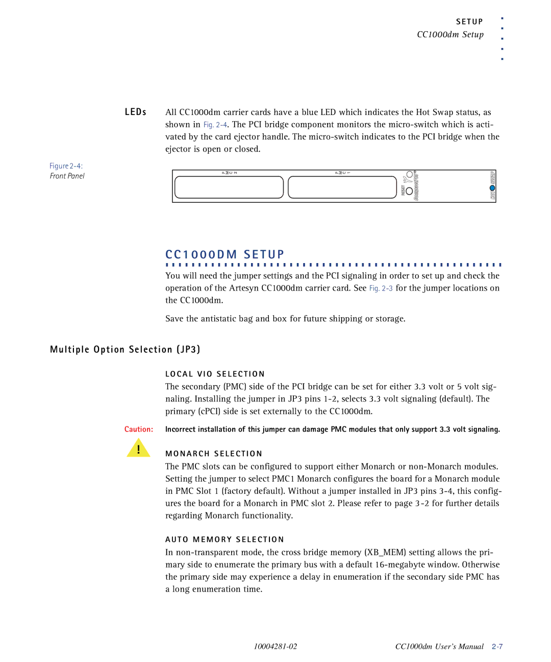
LEDs All CC1000dm carrier cards have a blue LED which indicates the Hot Swap status, as shown in Fig.
Figure
Front Panel
.C.C.1. 0. .0.0. D. .M. . .S.E.T. U. .P. . . . . . . . . . . . . . . . . . . . . . . . . . . . . . . . . .
You will need the jumper settings and the PCI signaling in order to set up and check the operation of the Artesyn CC1000dm carrier card. See Fig.
Save the antistatic bag and box for future shipping or storage.
Multiple Option Selection (JP3)
Caution:
!
L O C A L V I O S E L E C T I O N
The secondary (PMC) side of the PCI bridge can be set for either 3.3 volt or 5 volt sig- naling. Installing the jumper in JP3 pins
Incorrect installation of this jumper can damage PMC modules that only support 3.3 volt signaling.
M O N A R C H S E L E C T I O N
The PMC slots can be configured to support either Monarch or
A U T O M E M O R Y S E L E C T I O N
In
CC1000dm User’s Manual |