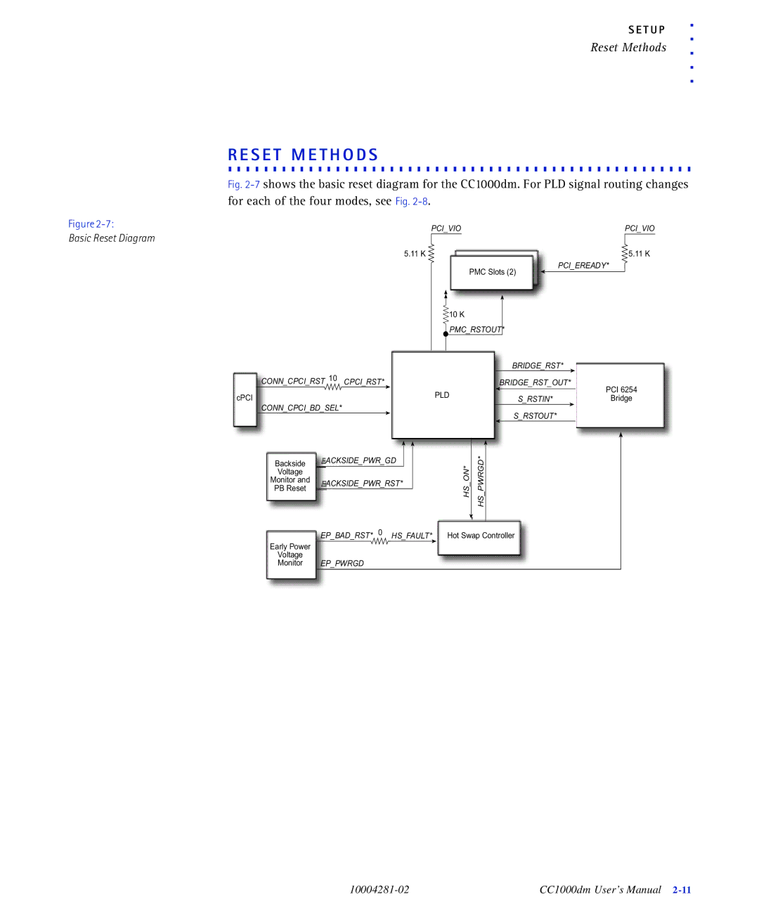
Dual Mode PMC cPCI Carrier Card User’s Manual
CC1000dm
The information in this manual has been checked and is believed to be
REGULATORY AGENCY WARNINGS & NOTICES
Issue date May 10
R e g u l a t o r y
EC Declaration of Conformity
According to EN Manufacturer’s Name Artesyn Technologies
2 Setup
CONTENTS
Components and Features Functional Overview Additional Information
CC1000dm Setup
PCI Bridge Features PMC Module Installation
Technical Support Service Information
Features Data Buffers Arbitration and Device Selection
C o n t e n t s
General System Block Diagram
FIGURES
Basic Reset Diagram
PLD Signal Routing-All Modes
10004281-02
F i g u r e s
vi CC1000dm User’s Manual
2-10
TABLES
2-10
3-11
10004281-02
Ta b l e s
viii CC1000dm User’s Manual
PCI6254 Configuration Registers-Non-Transparent Mode
PCI6254 Configuration Registers-Transparent Mode
REGISTERS
Internal Arbiter Control Register
10004281-02
R e g i s t e r s
2 CC1000dm User’s Manual
OVERVIEW
C.O. M. .P. O. .N. E. .N. T. S. . A. .N. D. . .F.E.A. T. .U.R. E. .S
Functional Overview
F.U.N. .C.T.I.O. N. .A. L. . O. .V.E. R. .V.I.E.W
A.D. D. .I T. .I O. .N. A. .L. .I .N.F. O. .R.M. .A. T. .I O. .N
Additional Information
Product Certification
RoHS Compliance
Additional Information
Terminology and Notation
Technical References
Document
Additional Information
O V E R V I E W
Additional Information
C.C.1. 0. .0.0. D. .M. . .C.I.R.C. U. .I T. . B. .O. A. .R.D
SETUP
E.L.E.C. .T.R.O. S. .T.A. T. I. C. . D. .I .S.C.H. .A.R. G. .E
S E T U P
CC1000dm Circuit Board
Component Map, Top rev
2-2 CC1000dm User’s Manual
Component Map, Bottom rev
CC1000dm Circuit Board
10004281-02
S E T U P
CC1000dm Circuit Board
Identification Numbers Connectors
CC1000dm Circuit Board
Fuses and Jumpers
Jumper/Header Locations, Top View
CC1000dm Circuit Board
S E T U P
PMC2 PMC1 9 JP2 1 PMC2 JTAG Header 10 2 PMC1 JTAG Header
CC1000dm Setup
C.C.1. 0. .0.0. D. .M. . .S.E.T. U. .P
Multiple Option Selection JP3
Multiple Option Jumper, JP3
CC1000dm Setup
Multiple Option Jumper
Selection, JP3
Signal Name
CC1000dm Setup
Signal
Signal
O.P. E. R. .A. T. I.O. .N.A. .L. .C.H. E. .C.K. S
Power Requirements
Environmental Considerations
Operational Checks
Reset Methods
R.E.S. E. .T. .M. E. .T.H. O. .D.S
Basic Reset Diagram
EPBADRST* 0 HSFAULT* Hot Swap Controller
Any of the following methods reset the entire board
Reset Methods
Troubleshooting
T.R.O. U. .B. L. E. .S.H. O. .O. T. I. N. .G
S E T U P
Troubleshooting
PMC/PCI INTERFACE
P.C.I. .B.R. I.D. G. .E. .F.E. A. .T.U. R. .E.S
P.M. .C. .M. .O.D. .U.L.E. .I.N. S. .T.A. L. L. .A.T.I.O. N
PMC Module Installation
Device Mapping
PMC Module Installation
Timing Interrupts
Internal Arbiter Control Register
PMC Module Installation
Register
to… 1001 PCI 6254 has highest priority 1010-1111 reserved
PMC Module Installation
Bridge EEPROM
B.R.I.D. G. .E. .E.E. P. .R.O. M
PCI 6254 Configuration Registers
PCI6254 Configuration Registers Non-Transparent Mode
PCI 6254 Configuration Registers
P M C / P C I I N T E R F A C E
Register
reserved
PCI 6254 Configuration Registers
Secondary Status
10004281-02
P M C / P C I I N T E R F A C E
PCI 6254 Configuration Registers
PCI Identification Values
P.C.I. .I D. .E.N. .T.I .F.I C. .A. T. I.O. .N. .V. A. .L.U. E. .S
J .T.A.G. . H. .E.A. D. .E.R. S
PCI Bus Control Signals
P.C.I. .B.U. S. . C. .O. N. .T.R. O. .L. .S.I.G. N. .A.L. S
PMC INTERRUPTS A, B, C, D lines are used to interrupt the CPU
PCI Bus Control Signals
Each PMC expansion slot has four 64-pin connectors, see Table
PMC Connector Pin Assignments
J2x PMC Connector Pin Assignments
PMC Connector Pin Assignments
J13 J14 Pin
PMCRSTOUT
P M C / P C I I N T E R F A C E
PMC Connector Pin Assignments
D.A. T. A. . .B.U. F. .F.E.R. S
CARRIER CARD BUS INTERFACE
F.E.A. T. .U.R. E. .S
Arbitration and Device Selection
C.L.O. C. .K. .G. E. .N. E. R. .A.T. I.O. .N
H.O. T. . S. .W. .A.P
Hot Swap
Hot Swap Controller HSC on the system board Staged backplane pins
Hot Swap
Implementation
CC1000dm Control Signals
C.C.1. 0. .0.0. D. .M. . .C.O. N. .T.R. O. .L. .S.I.G. N. .A. L. S
J2 Connector Pin Assignments
Backplane Connector Pin Assignments
C A R R I E R C A R D B U S I N T E R F A C E
Row Z
J3 Connector Pin Assignments
Backplane Connector Pin Assignments
Row Z Row A
Row B
J5 Connector Pin Assignments
Backplane Connector Pin Assignments
C A R R I E R C A R D B U S I N T E R F A C E
Row A
Row A
Backplane Connector Pin Assignments
Row B
Row C
C A R R I E R C A R D B U S I N T E R F A C E
Backplane Connector Pin Assignments
ASCII
GLOSSARY
cPCI
ETSI
Vital Product Data
G l o s s a r y
5-2 CC1000dm User’s Manual
10004281-02
Numerics
INDEX
I n d e
Page
w w w. a r t e s y n c p . c o m
CC1000dm User’s Manual
Madison, WI 53717-1935 USA
International Sales & Support +44 131