Timing
Interrupts
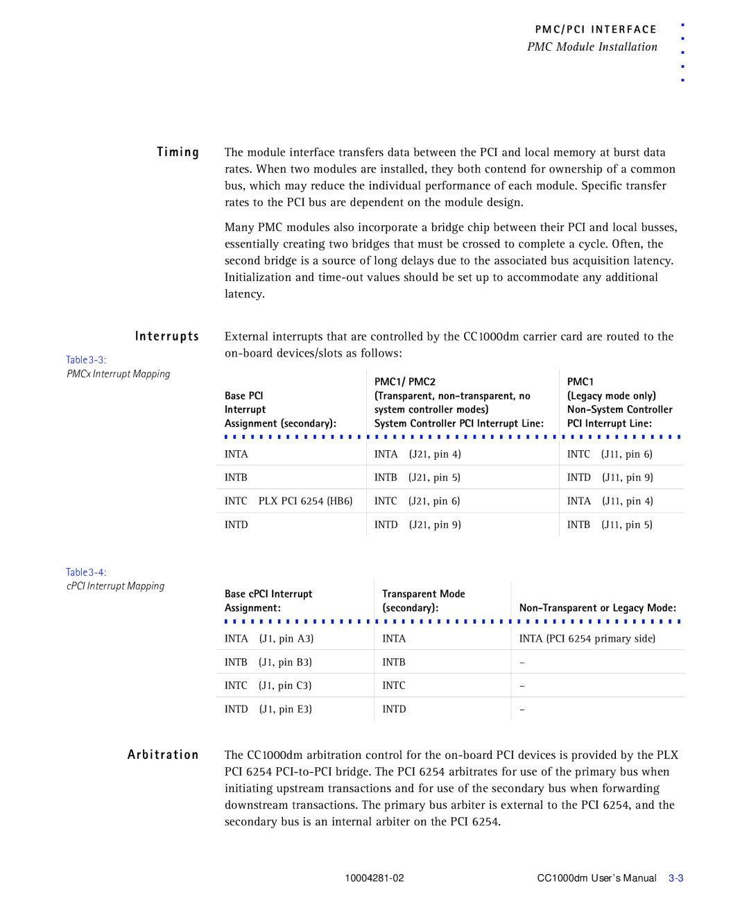
Table
PMCx Interrupt Mapping
P M C / P C I I N T E R F A C E | . | |
. | ||
PMC Module Installation | ||
. | ||
| ||
| . . |
The module interface transfers data between the PCI and local memory at burst data rates. When two modules are installed, they both contend for ownership of a common bus, which may reduce the individual performance of each module. Specific transfer rates to the PCI bus are dependent on the module design.
Many PMC modules also incorporate a bridge chip between their PCI and local busses, essentially creating two bridges that must be crossed to complete a cycle. Often, the second bridge is a source of long delays due to the associated bus acquisition latency. Initialization and
External interrupts that are controlled by the CC1000dm carrier card are routed to the
| PMC1/ PMC2 | PMC1 |
Base PCI | (Transparent, | (Legacy mode only) |
Interrupt | system controller modes) | |
Assignment (secondary): | System Controller PCI Interrupt Line: | PCI Interrupt Line: |
|
|
|
INTA | INTA | (J21, pin 4) | INTC | (J11, pin 6) | |
|
|
|
|
|
|
INTB |
| INTB | (J21, pin 5) | INTD | (J11, pin 9) |
|
|
|
|
|
|
INTC | PLX PCI 6254 (HB6) | INTC | (J21, pin 6) | INTA | (J11, pin 4) |
|
|
|
|
| |
INTD | INTD | (J21, pin 9) | INTB | (J11, pin 5) | |
|
|
|
|
|
|
Table
cPCI Interrupt Mapping
Base cPCI Interrupt |
| Transparent Mode |
|
| |
Assignment: |
| (secondary): |
| ||
INTA | (J1, pin A3) |
| INTA |
| INTA (PCI 6254 primary side) |
|
| ||||
|
|
|
|
|
|
INTB | (J1, pin B3) |
| INTB |
| – |
|
|
|
|
|
|
INTC | (J1, pin C3) |
| INTC |
| – |
|
|
|
|
|
|
INTD | (J1, pin E3) |
| INTD |
| – |
|
|
|
|
|
|
Arbitration The CC1000dm arbitration control for the
CC1000dm User’s Manual |