J23:
J24:
Fuses and Jumpers
Note:F5:
Fuses F5 through F10 are
located on the bottom side, | F6: | |
| ||
see Fig. |
| F7: |
|
| |
|
| F8: |
|
| F9: |
|
| F10: |
| JP1, JP2: | |
|
| JP3: |
|
| JP5: |
|
| JP6: |
|
| JP7: |
S E T U P | . | |
. | ||
CC1000dm Circuit Board | ||
. | ||
| ||
| . . |
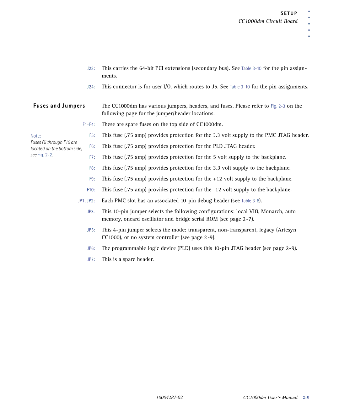
This carries the
This connector is for user I/O, which routes to J5. See Table
The CC1000dm has various jumpers, headers, and fuses. Please refer to Fig.
These are spare fuses on the top side of CC1000dm.
This fuse (.75 amp) provides protection for the 3.3 volt supply to the PMC JTAG header. This fuse (.75 amp) provides protection for the PLD JTAG header.
This fuse (.75 amp) provides protection for the 5 volt supply to the backplane. This fuse (.75 amp) provides protection for the 3.3 volt supply to the backplane. This fuse (.75 amp) provides protection for the +12 volt supply to the backplane. This fuse (.75 amp) provides protection for the
This
This
The programmable logic device (PLD) uses this
CC1000dm User’s Manual |
