Liebert Challenger ITR
Table i Product model information
Split system configurations
Table iii Self-contained system configurations
Table of Contents
Refrigeration Systems
AIR-COOLEDSYSTEM-STANDARD and Optional Features
Glycool SYSTEMS-STANDARD and Optional Features
Optional EQUIPMENT-ALLSYSTEMS
Comprehensive Monitoring SYSTEMS-OPTIONAL
Comprehensive Monitoring SOLUTIONS-OPTIONAL
System Data Dimensional Drawings Electrical Data
Figures
Page
Page
Humidity Control
Temperature Control
Air Volume
Air Filtration
Efficiency in Economic Terms
Multiple Configurations to Fit a Variety of Spaces
Liebert Challenger ITR
Unit configurations
Image is Illustrative only
Control Type
Diagnostics
Control
Internal System Control
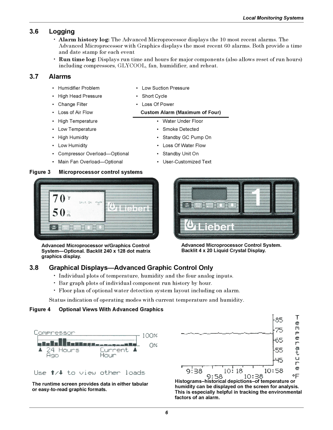
Logging
Alarms
Custom Alarm Maximum of Four
Graphical Displays-Advanced Graphic Control Only
Fan Section
Cabinet and Frame
Electrical Panel
Infrared Humidifier
Condensate Pump
Remote Temperature/ Humidity Sensors
Disconnect Switch-Locking Type
Condensate pump capacity
Chilled Water System-Standard Features
Chilled Water System-Optional Features
Split Systems
Refrigeration System Components-Standard Features
Self-Contained Systems
Air-Cooled, Self-Contained Systems-Standard Features
Air-Cooled, Self-Contained Systems-Optional Features
Centrifugal Fan, Condensing Unit
Air-Cooled Split Systems-Standard Features
Air-Cooled Split Systems-Optional Features
Propeller Fan Condensing Unit
Water/Glycol Self-Contained Systems-Standard Features
Water/Glycol Split System-Standard Features
Glycol Pump
Water/Glycol-Cooled, Split System-Optional Features
Factory Installed Non-Fused Disconnect Switch
Glycool System-Standard Features
GLYCOOL-Self-Contained Models Only
Quiet-Line Drycoolers
Glycol and GLYCOOL-Cooled-Optional Equipment
Drycooler
Evaporator Coil Econ-O-Coil Three-way Glycool Control Valve
Steam generating humidifier Adjustable Floor Stand
Steam Generating Humidifier
High External Static Blowers
SCR Reheat
High-Efficiency Filter
High-Efficiency Motors
Hot Water Reheat
Smoke Detector
Firestat
Firestat
Network Monitoring Systems
Stand-Alone Monitoring and Leak Detection Solutions
Enterprise Monitoring Systems
Leak Detection Modules
Discrete Output Interface Card
Liebert Nform
Liebert SiteScan Web
Liebert SiteLink
Environmental Discrete Outputs Card
Leak Detection
Temperature and Humidity Recorder
Universal Monitor
Liebert Challenger ITR air-cooled data-60 Hz
BR 067A BR 060E
Infrared Humidifier Standard
Fan Data Blower A12x9AT
Liebert Challenger ITR air-cooled data-50 Hz
System Type Split Systems
Evaporator Coil V-Frame, at Standard Conditions
Condenser Air 35C 95F Ambient
Liebert Challenger ITR air-cooled data-50Hz
Connection Sizes Challenger ITR Unit
Indoor Unit BR 071WG BR 060E Net Capacity Data
Liebert Challenger ITR water cooled data, 60 Hz
System Type Self-Contained Split Systems
Connection Sizes Remote Condensing Unit
Water Regulating Valve
Water Requirements Coaxial Condenser
Liebert Challenger ITR water cooled data, 50 Hz
BTU/H
Capacity, kg/hr lb/hr
Liebert Challenger ITR glycol cooled data, 60 Hz
Glycool
Indoor Unit
Steam Generating Humidifier Optional
Liebert Challenger ITR glycol cooled data, 50 Hz
Glycool
Drycooler 35C 95F Ambient
Glycol Pump 3-Phase kW hp
System Type Glycol Cooled
Liebert Challenger ITR chilled water data, 60 Hz
Indoor Unit BR 102C Fan Data Blower A12x9AT
Liebert Challenger ITR chilled water data, 50 Hz
Indoor Unit BR 101C
Dimensional Drawings
50 Hz 60 Hz Unit Weight Models Lb. kg
Optional Floor Stand
Model Net Weight 60 Hz 50 Hz Lbs kg MC69W MC68W
SL-11081
36-1/4
Liebert Lee-Temp Receiver = 40 1016mm = 7-1/2 190mm
Electrical Data
Liebert Challenger ITR electrical data1-60 Hz
Motor Hp 2.2 kW
Self-contained with SCR reheat
Motor Hp 1.5 kW
Electric Reheat Only Motor Hp 1.1 kW
Voltage 208 230 460 575 60 Hz Scroll Compressor
Scroll compressor and main fan for comparison purposes only
Outdoor condensing units
Main Fan Motor Hp 1.1 kW
Indoor condensing units, water-cooled
Outdoor condensing units-Quiet-Line
Indoor condensing units, air-cooled
Drycooler and pump package 95F 35C ambient
Fan speed control condensers
Liebert Lee-Temp condensers
Voltage 208/230 460 575 Glycol
Liebert Challenger ITR electrical data-50 Hz
Scroll compressor and main fan for comparison only
Indoor condensing units air-cooled
Indoor condensing units water-cooled
Pumps
Drycooler only 35C 95F ambient, three-phase
Drycooler only 35C 95F ambient, single phase
Submittals
Summary
Design Requirements
All Systems
Advanced Microprocessor Control Standard
Common Alarm
Alarms
Audible Alarm
Diagnostics
Advanced Microprocessor Control with Graphics Optional
Communications
Alarms
Electric Reheat Standard
Infrared Humidifier Standard
Steam Generating Humidifier Optional
Hot Water Reheat Optional
Direct Expansion Self-Contained Systems
Centrifugal Fan Condenser Optional
Fan Speed Control FSC Head Pressure Control Standard
Liebert Lee-Temp Head Pressure Control Optional
Two-way Water Regulating Valve with Bypass Standard
Outdoor Unit
Glycool Self-Contained Systems
Optional Disconnect
Direct Expansion Split Systems
Centrifugal Fan Condensing Unit
Ton Models
Optional High Ambient Models
Water or Glycol-Cooled Split Systems
Optional Quiet-Line Models
Water or Glycol-Cooled Condensing Unit
Three-way Chilled Water Valve Standard
Flow Switch Optional
Chilled Water Self-Contained Systems Chilled Water Coil
Two-way Chilled Water Valve Optional
Field Quality Control
Comprehensive Monitoring Solutions
Installation of Environmental Control Units
Page
Ti n
Ne t
Iti
That

