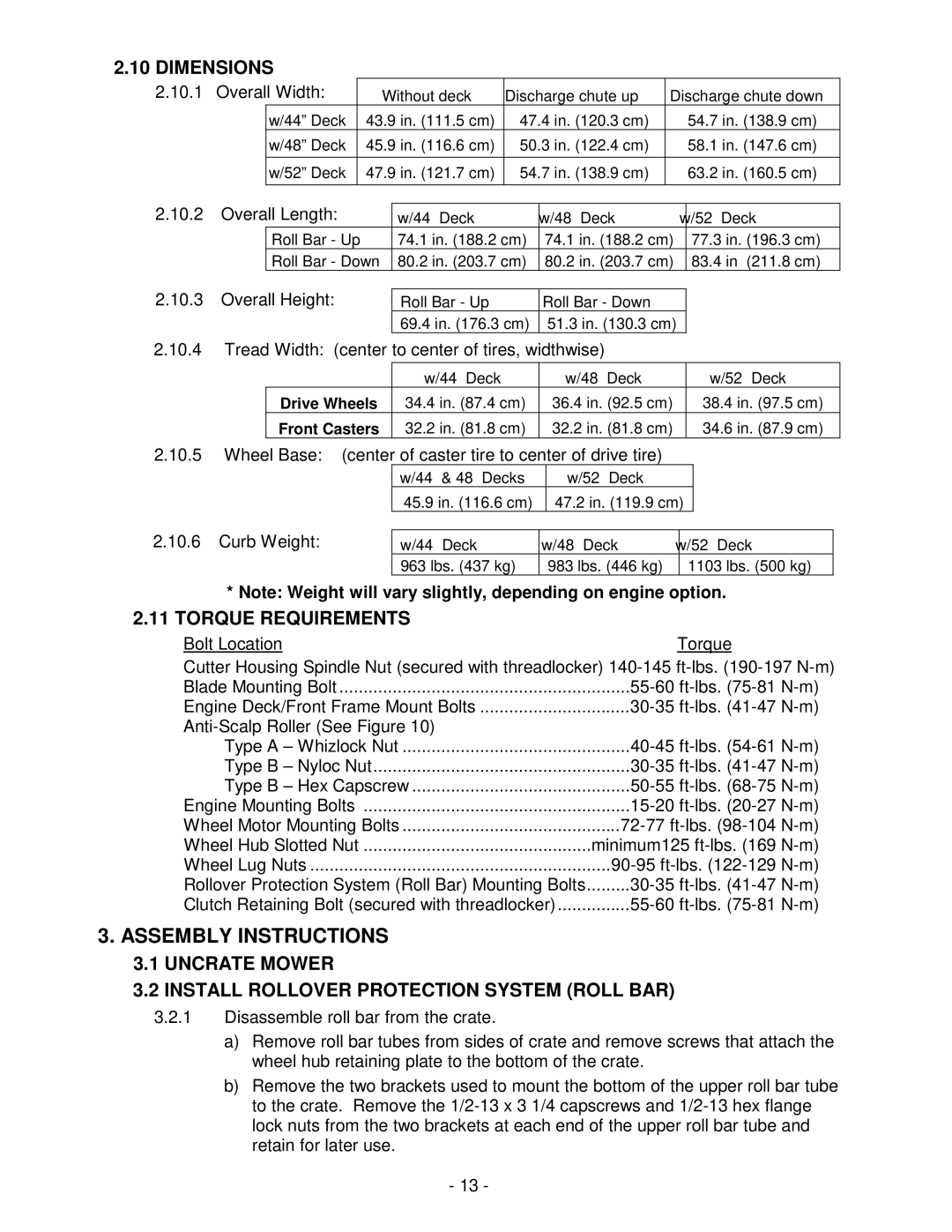
Lazer ZHP specifications
The Exmark Lazer ZHP is a professional-grade zero-turn mower designed to deliver unparalleled performance and efficiency for commercial landscaping and maintenance. Recognized for its durability and innovative features, the Lazer ZHP series has become a preferred choice for professionals seeking precision and reliability in their mowing equipment.One of the standout features of the Exmark Lazer ZHP is its powerful engine options, which typically include models from trusted manufacturers such as Kohler and Kawasaki. These engines are designed to provide robust performance while ensuring fuel efficiency, allowing operators to cover large areas without frequent refueling. The Lazer ZHP also boasts a high-capacity fuel tank, enhancing productivity by minimizing downtime due to refueling.
The mower’s cutting deck is another key highlight, with options typically ranging from 48 to 72 inches in size. The Exmark patented UltraCut deck technology provides an exceptional cut quality, ensuring that grass is finely mulched and evenly distributed. This not only enhances the visual appeal of the lawn but also contributes to overall lawn health by returning valuable nutrients to the soil.
In terms of comfort and ergonomics, the Lazer ZHP is built with the operator in mind. The spacious operator platform is designed to reduce fatigue during long hours of operation. The mower features an adjustable seat with premium cushioning, and the controls are intuitively positioned for easy access. The ergonomic design enhances maneuverability, allowing the operator to navigate tight spaces and obstacles with ease.
Technologically, the Exmark Lazer ZHP incorporates advanced features such as the Exmark patented IS (Independent Suspension) system. This technology enhances ride quality and stability, reducing the impact of uneven terrain on the operator and improving cut quality. Additionally, the mower is equipped with a sophisticated hydrostatic transmission, allowing for seamless speed and directional changes that enhance control and precision.
Another notable characteristic of the Lazer ZHP is its rugged construction, designed to withstand the rigors of commercial use. The welded steel frame and heavy-duty components are engineered to provide long-lasting performance and reliability, even in the most challenging conditions. The durable design not only enhances the mower’s lifespan but also reduces maintenance costs over time.
In summary, the Exmark Lazer ZHP stands out in the market for its combination of power, technology, and durability. With features that cater specifically to the needs of professional landscapers, this mower promises exceptional results and a superior mowing experience, making it an essential addition to any landscaping fleet.
