Installationstallation, cont’d
Installation Overview
To install and set up a DDS 402 Digital Display Scaler for operation, perform the following steps:
1
2
3
4
5
6
Disconnect power from all of the equipment, including the video source(s), and the devices that will receive the scaled video signal.
Rack mount the scaler, if desired. See Mounting the Scaler in this chapter.
Connect the digital input and
Connect the digital output cables. See Video output connections in this chapter.
If desired, connect the
Connect the AC power cable. See Power connection in this chapter.
Mounting the Scaler
The DDS 402 comes with rubber feet and a set of rack mounting brackets.
Tabletop use
For tabletop use, attach a
Rack mounting
Rack mount the scaler as follows:
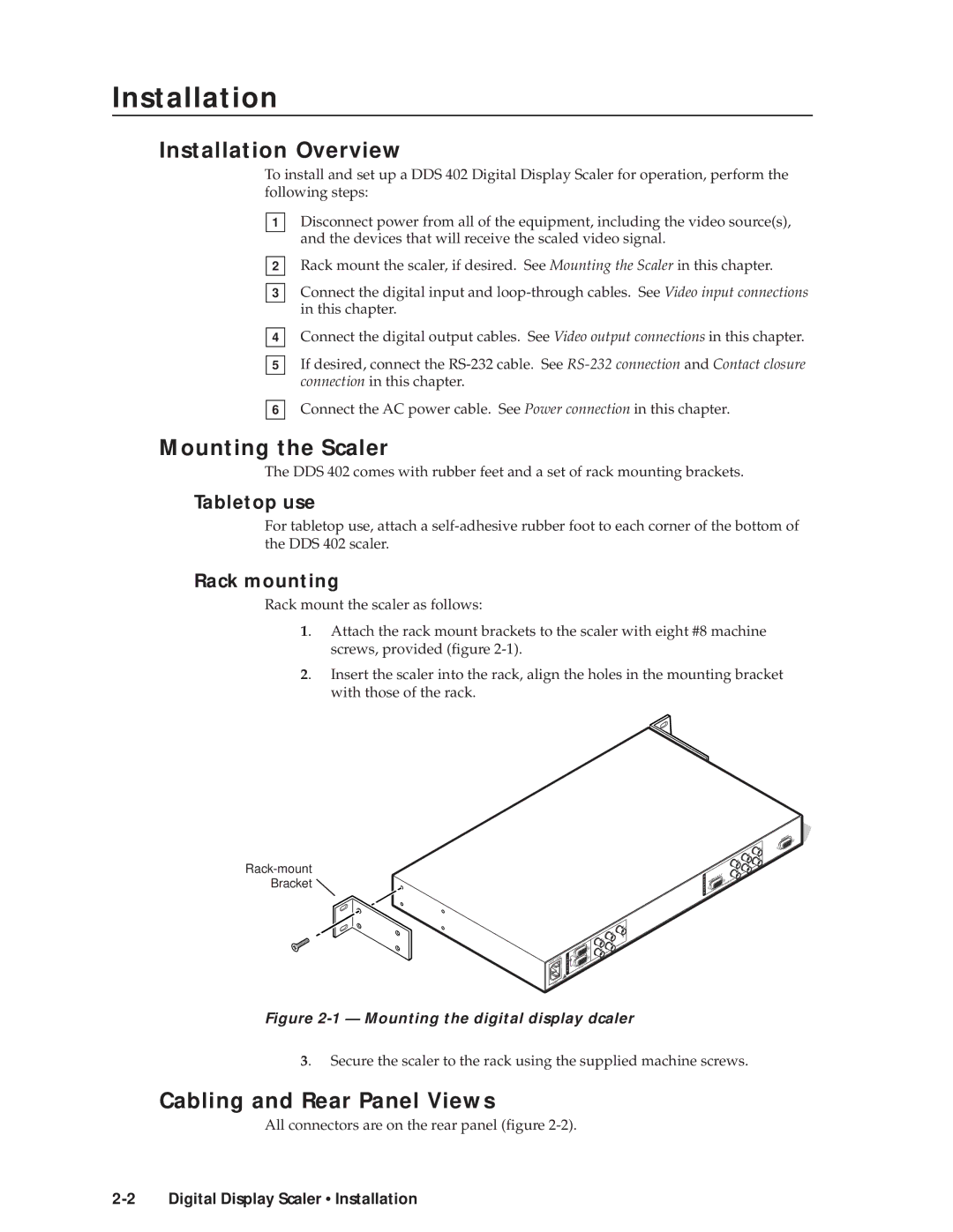
1. Attach the rack mount brackets to the scaler with eight #8 machine screws, provided (figure
2. Insert the scaler into the rack, align the holes in the mounting bracket with those of the rack.
![]()
1
I |
|
N |
|
P |
|
U | RGB |
T | |
S |
|
REMOTE
|
|
|
|
|
| B |
|
|
|
|
|
| |
|
|
|
|
|
| G |
|
|
|
|
|
| /Y |
|
|
|
|
|
| S |
|
|
|
|
| R |
|
|
|
|
|
| /RY | V |
|
|
|
|
| H |
|
|
| Y |
| Y | ||
O |
|
| ||||
U |
|
|
|
| ||
T | RGB/R |
|
| RGB/HD |
|
|
P |
|
|
|
|
| |
U |
|
|
|
|
|
|
T |
|
|
|
|
|
|
S |
|
|
|
|
|
|
|
|
| B | |
2 |
|
| /B |
|
|
| G |
|
|
|
| /Y | S |
|
R |
|
|
|
|
/RY |
| V |
|
|
|
|
|
| |
H |
| Y |
| |
B |
|
| ||
|
|
| ||
RGB/R |
|
|
|
|
Figure 2-1 — Mounting the digital display dcaler
3. Secure the scaler to the rack using the supplied machine screws.
Cabling and Rear Panel Views
All connectors are on the rear panel (figure