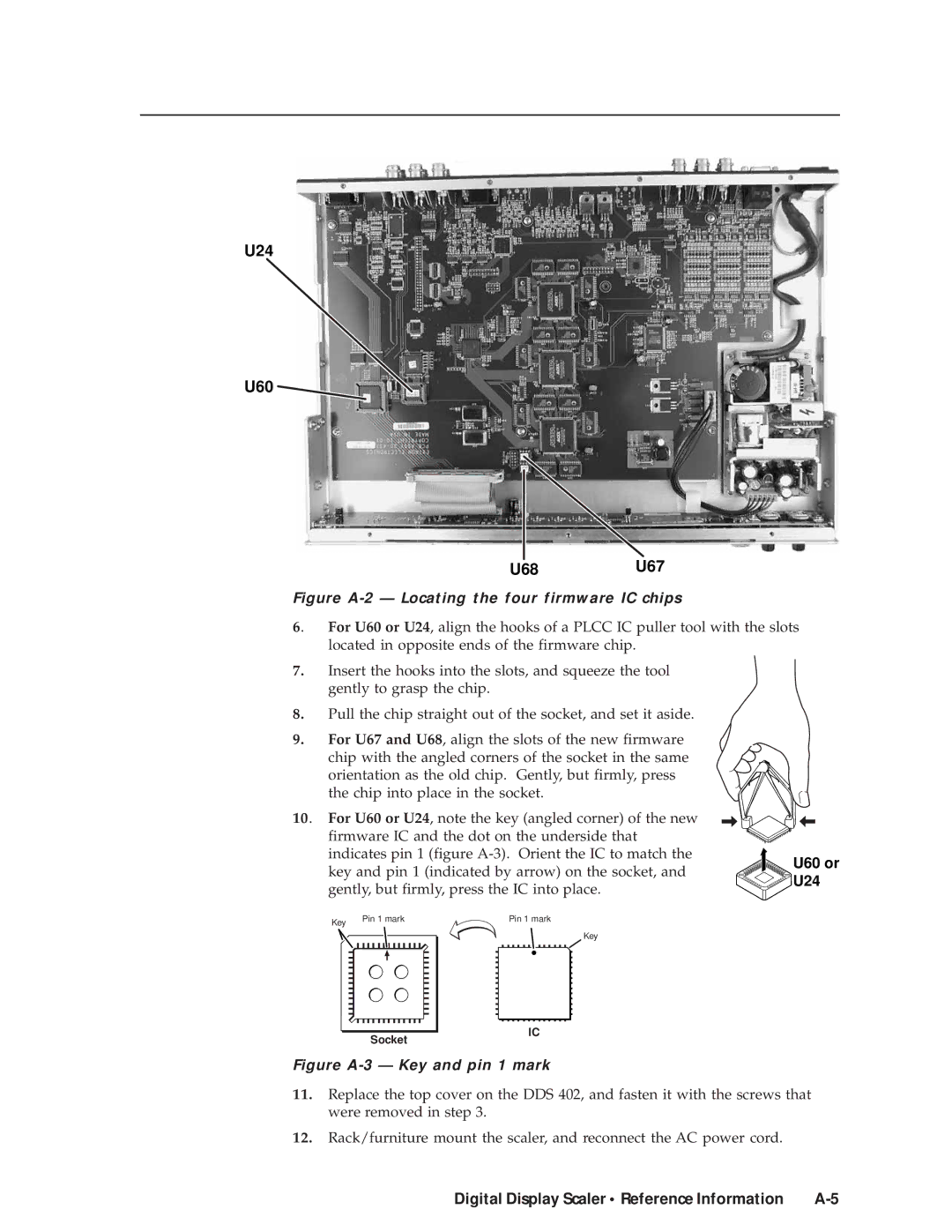
U24
U60
U68U67
Figure A-2 — Locating the four firmware IC chips
6. For U60 or U24, align the hooks of a PLCC IC puller tool with the slots located in opposite ends of the firmware chip.
7.Insert the hooks into the slots, and squeeze the tool gently to grasp the chip.
8.Pull the chip straight out of the socket, and set it aside.
9.For U67 and U68, align the slots of the new firmware chip with the angled corners of the socket in the same orientation as the old chip. Gently, but firmly, press the chip into place in the socket.
10. For U60 or U24, note the key (angled corner) of the new firmware IC and the dot on the underside that indicates pin 1 (figure
Key | Pin 1 mark | Pin 1 mark |
|
|
Key
U60 or


 U24
U24
Socket |
IC |
Figure A-3 — Key and pin 1 mark
11.Replace the top cover on the DDS 402, and fasten it with the screws that were removed in step 3.
12.Rack/furniture mount the scaler, and reconnect the AC power cord.
Digital Display Scaler • Reference Information |