Programmer’s Guide
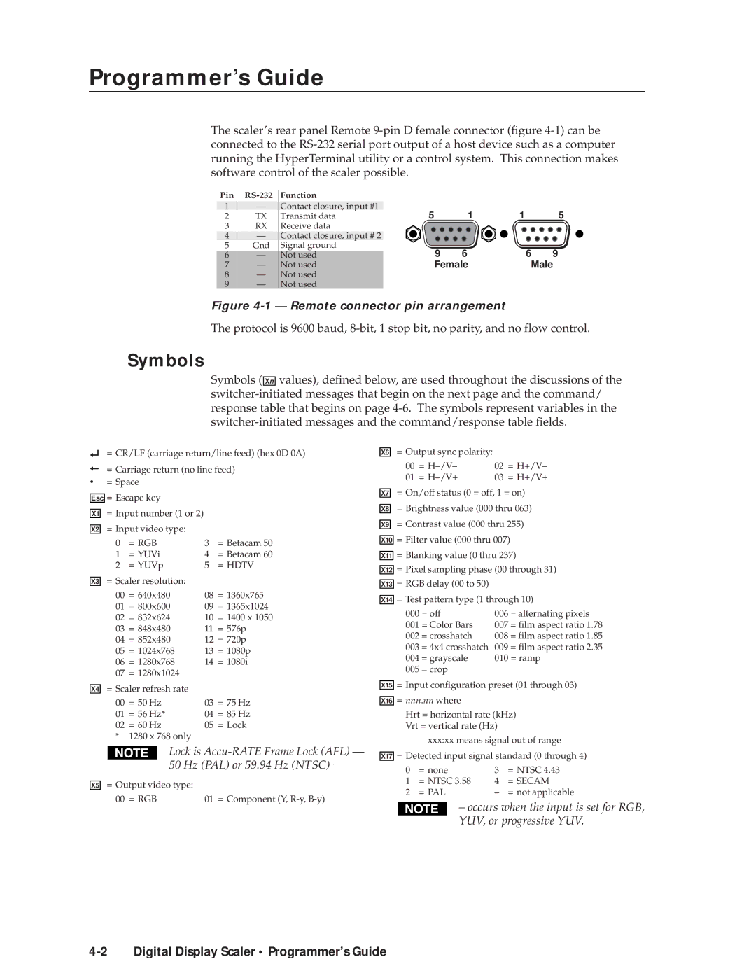
The scaler’s rear panel Remote
Pin | Function | |
1 | — | Contact closure, input #1 |
2 | TX | Transmit data |
3 | RX | Receive data |
4 | — | Contact closure, input # 2 |
5 | Gnd | Signal ground |
6 | — | Not used |
7 | — | Not used |
8 | — | Not used |
9 | — | Not used |
5 | 1 | 1 | 5 |
9 | 6 | 6 | 9 |
Female | Male | ||
Figure 4-1 — Remote connector pin arrangement
The protocol is 9600 baud,
Symbols
Symbols ( Xn values), defined below, are used throughout the discussions of the
|
| = CR/LF (carriage return/line feed) (hex 0D 0A) | |||
|
| = Carriage return (no line feed) | |||
• |
| = Space |
|
| |
| = Escape key |
|
| ||
Esc |
|
| |||
X1 | = Input number (1 or 2) |
|
| ||
X2 | = Input video type: |
|
| ||
|
| 0 | = RGB | 3 | = Betacam 50 |
|
| 1 | = YUVi | 4 | = Betacam 60 |
|
| 2 | = YUVp | 5 | = HDTV |
X3 |
| = Scaler resolution: |
|
| |
|
| 00 | = 640x480 | 08 | = 1360x765 |
|
| 01 | = 800x600 | 09 | = 1365x1024 |
|
| 02 | = 832x624 | 10 | = 1400 x 1050 |
|
| 03 | = 848x480 | 11 = 576p | |
|
| 04 | = 852x480 | 12 | = 720p |
|
| 05 | = 1024x768 | 13 | = 1080p |
|
| 06 | = 1280x768 | 14 | = 1080i |
|
| 07 | = 1280x1024 |
|
|
X4 | = Scaler refresh rate |
|
| ||
|
| 00 | = 50 Hz | 03 | = 75 Hz |
|
| 01 | = 56 Hz* | 04 | = 85 Hz |
|
| 02 | = 60 Hz | 05 | = Lock |
|
| * | 1280 x 768 only |
|
|
X6
X7
X8
X9
X10
X11
X12
X13
X14
X15
X16
= Output sync polarity: |
|
| |
00 | = | 02 | = H+/V– |
01 | = | 03 | = H+/V+ |
=On/off status (0 = off, 1 = on)
=Brightness value (000 thru 063)
=Contrast value (000 thru 255)
=Filter value (000 thru 007)
=Blanking value (0 thru 237)
=Pixel sampling phase (00 through 31)
=RGB delay (00 to 50)
=Test pattern type (1 through 10)
000 | = off | 006 | = alternating pixels |
001 | = Color Bars | 007 = film aspect ratio 1.78 | |
002 | = crosshatch | 008 | = film aspect ratio 1.85 |
003 | = 4x4 crosshatch | 009 | = film aspect ratio 2.35 |
004 | = grayscale | 010 = ramp | |
005 | = crop |
|
|
=Input configuration preset (01 through 03)
=nnn.nn where
Hrt = horizontal rate (kHz) Vrt = vertical rate (Hz)
xxx:xx means signal out of range
X5
Lock is Accu-RATE Frame Lock (AFL) — 50 Hz (PAL) or 59.94 Hz (NTSC) .
= Output video type: |
|
00 = RGB | 01 = Component (Y, |
X17
= Detected input signal standard (0 through 4)
0 | = none | 3 | = NTSC 4.43 |
1 | = NTSC 3.58 | 4 | = SECAM |
2 | = PAL | – | = not applicable |
– occurs when the input is set for RGB, YUV, or progressive YUV.
