Contents
Digital Display Scaler
DDS
Instrucciones de seguridad Español
Safety Instructions English
Consignes de Sécurité Français
Sicherheitsanleitungen Deutsch
QS-1
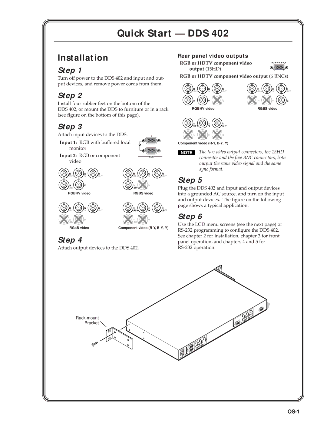
Rear panel video outputs
QS-2
Default display cycle
Quick Start DDS 402, cont’d
Main menu Input menu
Memory Presets menu
Output menu
QS-3
Exit menu
Advanced Configuration menu
Picture Adjustments menu
Executive Mode menu
Table of Contents
Table of Contents, cont’d
Digital Display Scaler Table of Contents Iii
Iv Digital Display Scaler Table of Contents
One
Digital Display Scaler Introduction
Introductiontroduction, cont’d
About this Manual
About the Scaler
Features
Introduction, cont’d
Digital Display Scaler Introduction
Introduction, cont’d
Two
Cabling and Rear Panel Views
Installationstallation, cont’d
Installation Overview
Mounting the Scaler
Video output connections
Video input connections
RS-232 connection
Installation, cont’d
Configuration
Power connection
Three
Input buttons
Front Panel Controls and Indicators
Operationeration, cont’d
Freeze button
Menu control buttons
Picture adjustment buttons
Adjustment knobs
LCD display
Button icons
Power
Operation, cont’d
Front Panel Operations
Input Configuration menu
Configuration
Pixel Phase submenu
Output Configuration menu
Input #2 submenu
Sync Polarity submenu
Resolution and refresh rates submenu
Resolution 50 Hz 56 Hz 60 Hz 75 Hz 85 Hz Lock at 50/60 Hz
Output Signal submenu
Erase Presets submenu
Save Presets submenu
Test Pattern submenu
Blue Mode submenu
RGB Delay submenu
Edge Smoothing submenu
Reset submenu
Picture adjustments
Adjust knobs have no mechanical limits to their rotation
Front panel security lockout executive mode
Optimizing the Video
Setting up a DVD source
Four
Digital Display Scaler Programmer’s Guide
Symbols
Scaler-Initiated Messages
Test pattern
RGB delay
Presets
Programmer’s Guide, cont’d
Scaler Error Responses
Using the Command/Response Table
Host-to-Scaler Instructions
Command Ascii Command Response Additional description
Command/response table for SIS commands
Command/response table for SIS commands cont’d
Test pattern
Command Ascii Command Response
Command/response table for special function SIS commands
Programmer’s Guide, cont’d
Five
Digital Display Scaler Scaler Software
Installing the software
Using the control program
Control Software for Windows
Control program I/O configuration window
Using the help program
Using the software
Scaler Software, cont’d
Button Label Generator
AAppendix a
Digital Display Scaler Reference Information
Specifications
Included parts Part number
Part Numbers
Included parts
Suggested part
Reference Information, cont’d
Firmware Upgrade Installation
U24 U60 U68U67
Button Labels
Installing labels in the scaler’s buttons
FCC Class a Notice Extron’s Warranty
Extron Electronics, USA