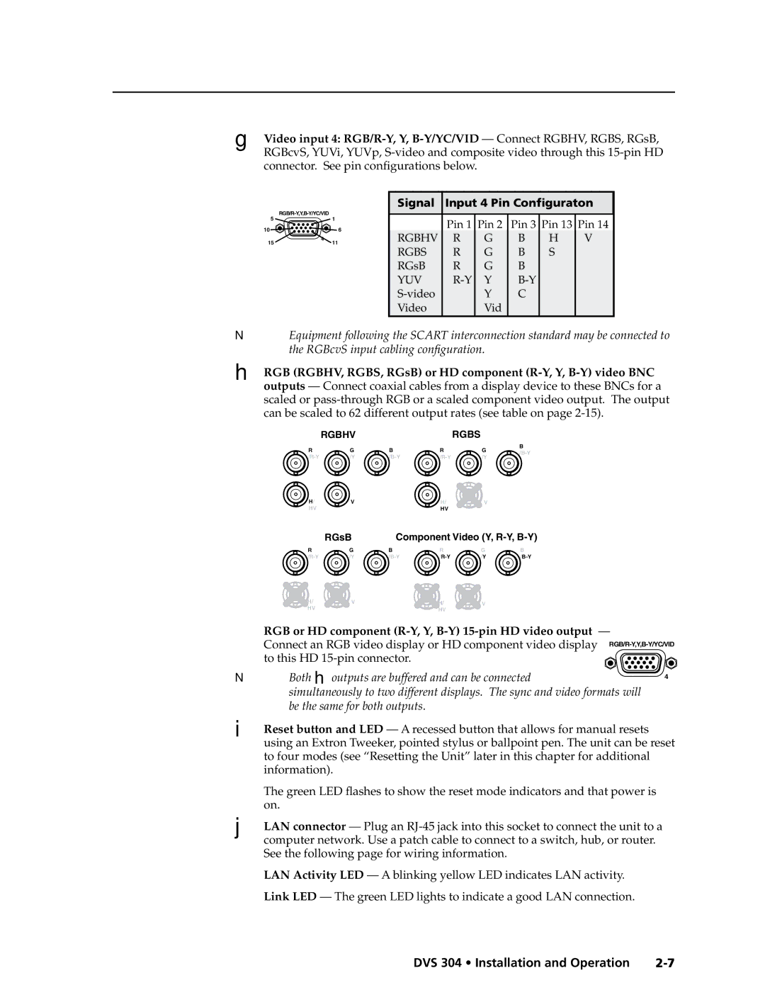
G | Video input 4: |
| RGBcvS, YUVi, YUVp, |
| connector. See pin configurations below. |
51
10 ![]()
![]()
![]() 6
6
4
1511
Signal | Input 4 Pin Configuraton | ||||
|
|
|
|
|
|
| Pin 1 | Pin 2 | Pin 3 | Pin 13 | Pin 14 |
RGBHV | R | G | B | H | V |
RGBS | R | G | B | S |
|
RGsB | R | G | B |
|
|
YUV | Y |
|
| ||
| Y | C |
|
| |
Video |
| Vid |
|
|
|
NEquipment following the SCART interconnection standard may be connected to the RGBcvS input cabling configuration.
H | RGB (RGBHV, RGBS, RGsB) or HD component |
| outputs — Connect coaxial cables from a display device to these BNCs for a |
| scaled or |
| can be scaled to 62 different output rates (see table on page |
|
| RGBHV |
|
| RGBS |
|
|
| R | G | B | R | G | B |
|
|
| ||||||
| /Y | /Y |
| ||||
|
|
| |||||
| H/ | V |
| H/ | V |
|
|
| HV |
|
| HV |
|
|
|
|
| RGsB | Component Video (Y, |
| |||
| R | G | B | R | G | B |
|
| /Y | /Y |
| ||||
| H/ | V |
| H/ | V |
|
|
| HV |
|
| HV |
|
|
|
| RGB or HD component |
| |||||
| Connect an RGB video display or HD component video display | ||||||
| to this HD |
|
|
|
| ||
N Both H outputs are buffered and can be connected | 4 | ||||||
|
|
|
|
|
|
| |
| simultaneously to two different displays. The sync and video formats will |
| |||||
| be the same for both outputs. |
|
|
|
| ||
I | Reset button and LED — A recessed button that allows for manual resets |
| |||||
| using an Extron Tweeker, pointed stylus or ballpoint pen. The unit can be reset | ||||||
to four modes (see “Resetting the Unit” later in this chapter for additional information).
| The green LED flashes to show the reset mode indicators and that power is |
| on. |
J | LAN connector — Plug an |
| computer network. Use a patch cable to connect to a switch, hub, or router. |
| See the following page for wiring information. |
| LAN Activity LED — A blinking yellow LED indicates LAN activity. |
| Link LED — The green LED lights to indicate a good LAN connection. |
DVS 304 • Installation and Operation |