Installation and Operation, cont’d
Start auto image
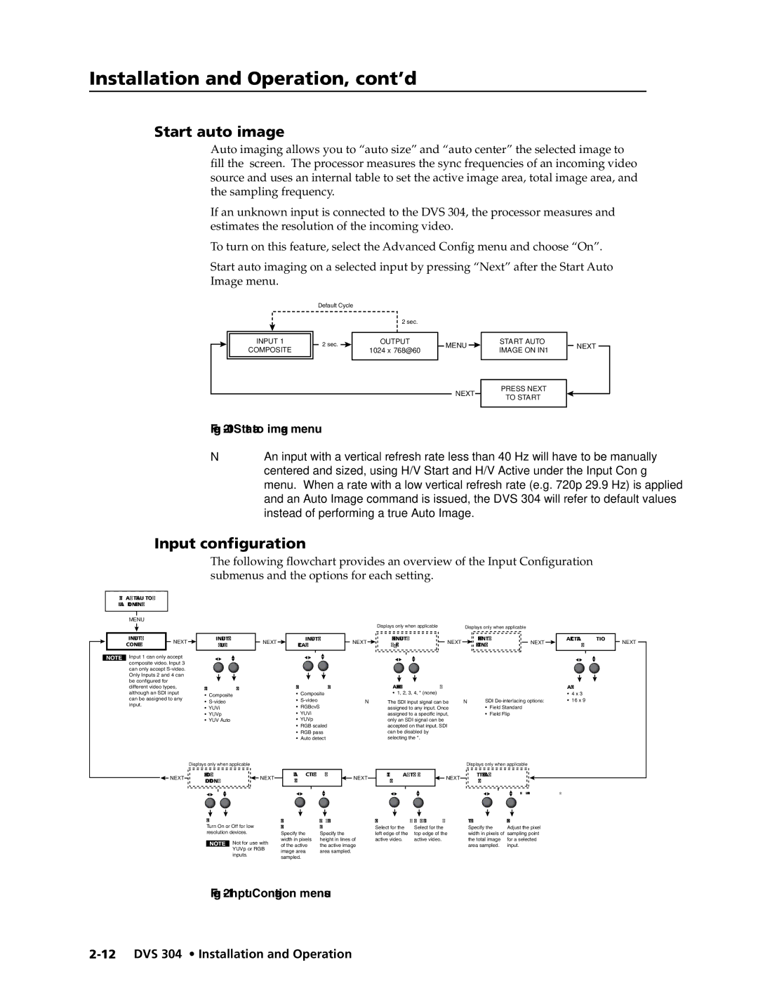
Auto imaging allows you to “auto size” and “auto center” the selected image to fill the screen. The processor measures the sync frequencies of an incoming video source and uses an internal table to set the active image area, total image area, and the sampling frequency.
If an unknown input is connected to the DVS 304, the processor measures and estimates the resolution of the incoming video.
To turn on this feature, select the Advanced Config menu and choose “On”.
Start auto imaging on a selected input by pressing “Next” after the Start Auto Image menu.
Default Cycle
2 sec.
INPUT 1 | 2 sec. | OUTPUT | MENU | |
COMPOSITE | 1024 x 768@60 | |||
|
| |||
|
|
| NEXT |
START AUTO IMAGE ON IN1
PRESS NEXT TO START
NEXT
Figure 2-10 — Start auto image menu
NAn input with a vertical refresh rate less than 40 Hz will have to be manually centered and sized, using H/V Start and H/V Active under the Input Config menu. When a rate with a low vertical refresh rate (e.g. 720p 29.9 Hz) is applied and an Auto Image command is issued, the DVS 304 will refer to default values instead of performing a true Auto Image.
Input configuration
The following flowchart provides an overview of the Input Configuration submenus and the options for each setting.
START AUTO |
| |
IMAGE ON IN1 |
| |
MENU |
| |
INPUT | NEXT | |
CONFIG | ||
|
Input 1 can only accept composite video. Input 3 can only accept
INPUT 2
YUVi
Select video format
•Composite
•
•YUVi
•YUVp
•YUV Auto
|
|
| Displays only when applicable |
| Displays only when applicable |
|
|
| |
NEXT | INPUT 4 | NEXT | SDI INPUT | NEXT | SDI | NEXT | ASPECT RATIO | NEXT | |
RGB SCALED | <*> 1 2 3 4 | FIELD STNDRD | 4x3 | ||||||
|
|
|
|
| |||||
| Select video format |
| Assign SDI to Input # |
|
|
| Aspect ratio options |
| |
| • Composite |
| • 1, 2, 3, 4, * (none) |
|
|
| • 4 x 3 |
|
• | N The SDI input signal can be | NSDI | • 16 x 9 | ||
• | RGBcvS | assigned to any input. Once | • | Field Standard |
|
• YUVi | assigned to a specific input, | • | Field Flip |
| |
• YUVp | only an SDI signal can be |
|
|
| |
• | RGB scaled | accepted on that input. SDI |
|
|
|
• RGB pass | can be disabled by |
|
|
| |
• | Auto detect | selecting the *. |
|
|
|
Displays only when applicable
Displays only when applicable
![]() NEXT
NEXT
FILM MODE | NEXT | H ACTIVE V | NEXT | H START | V | NEXT | TTLPIX PHASE | |||
<OFF> ON | XXX | XXX | 50 | 33 | XXXX | 08 | ||||
|
|
| ||||||||
|
|
|
|
|
|
|
|
| For YUVp or RGB input only | |
Film mode |
| Horizontal | Vertical active |
| Horizontal start | Vertical start |
| Total pixels | Pixel phase | |
Turn On or Off for low |
| active pixels | lines |
| Select for the | Select for the |
| Specify the | Adjust the pixel | |
resolution devices. |
| Specify the | Specify the |
| left edge of the | top edge of the | width in pixels of | sampling point | ||
Not for use with | width in pixels | height in lines of | active video. | active video. |
| the total image | for a selected | |||
of the active | the active image |
|
|
| area sampled. | input. | ||||
YUVp or RGB |
|
|
| |||||||
image area | area sampled. |
|
|
|
|
|
| |||
inputs. |
|
|
|
|
|
|
| |||
| sampled. |
|
|
|
|
|
|
| ||
|
|
|
|
|
|
|
|
| ||