Installation and Operation, cont’d
Rear Panel Features
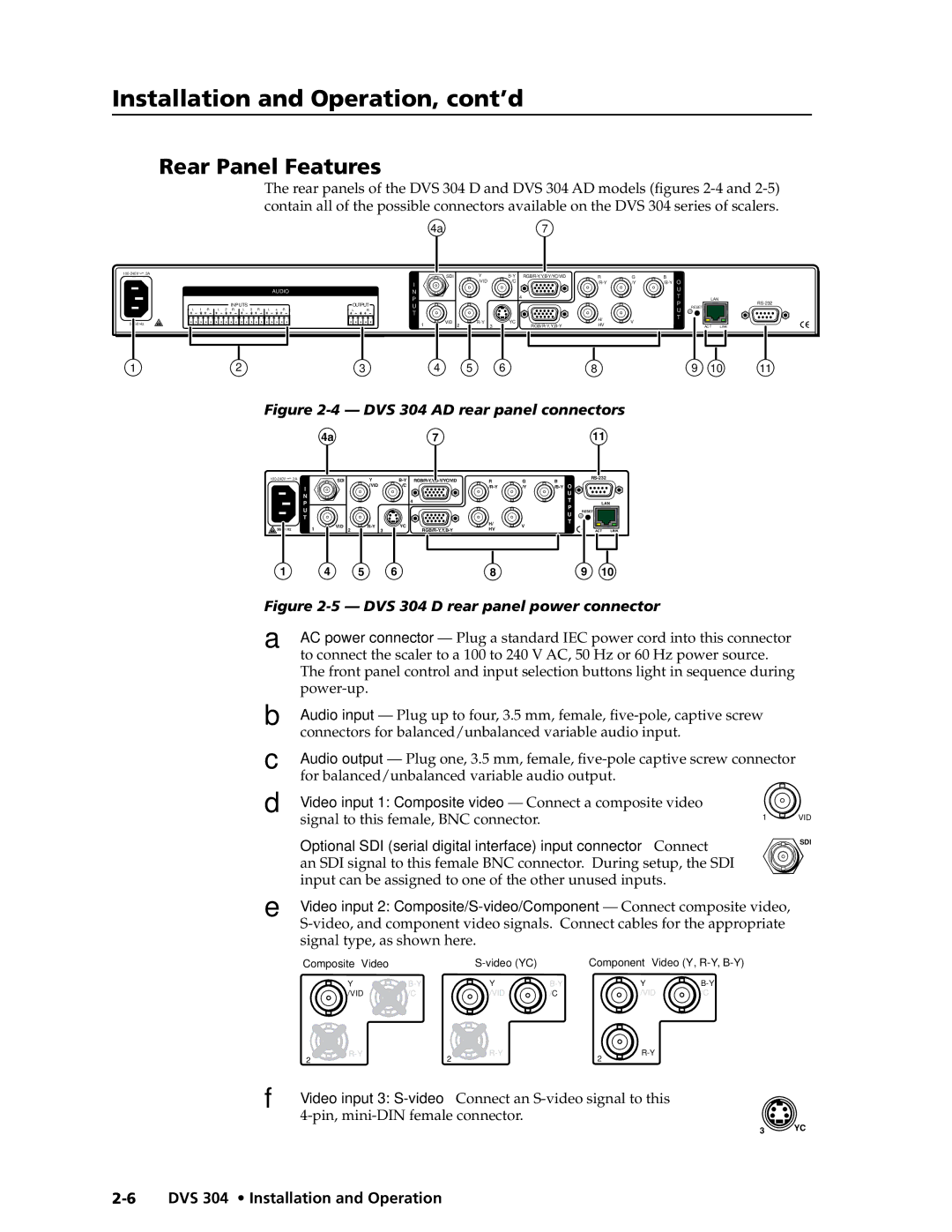
The rear panels of the DVS 304 D and DVS 304 AD models (figures
![]() .3A
.3A
L 1 R
50/60 Hz
INPUTS
L 2 R L 3 R
AUDIO
L 4 R
OUTPUT
L R
| 4a |
|
| 7 |
|
|
|
|
|
|
| SDI | Y | R | G | B | OO |
|
| ||
I |
| /VID | /C |
| /Y |
|
| |||
|
|
|
|
|
|
| UU |
|
| |
N |
|
|
|
|
|
|
|
|
| |
|
|
| 4 |
|
|
| TT |
|
| |
P |
|
|
|
|
|
| LAN |
| ||
|
|
|
|
|
|
| PP | |||
U |
|
|
|
|
|
|
| RESET | ||
|
|
|
|
|
|
| UU |
| ||
T |
|
|
|
|
|
|
|
|
| |
|
|
|
| H/ |
|
| T |
|
| |
| VID 2 | YC |
| V |
| T |
|
| ||
1 | HV |
|
| ACT | LINK |
1 | 2 | 3 | 4 | 5 | 6 | 8 | 9 | 10 | 11 |
Figure 2-4 — DVS 304 AD rear panel connectors
4a | 7 | 11 |
![]() .3A
.3A
I
N
P
U
T
50/60 Hz | 1 |
SDI | Y |
| /VID |
VID 2 |
R | G | B |
| ||
|
| ||||
/C | /Y | O |
| ||
|
|
|
| U |
|
4 |
|
|
| T | LAN |
|
|
|
| P | RESET |
|
|
|
| U | |
|
|
|
|
| |
YC | H/ | V |
| T |
|
HV |
|
|
| ACT LINK |
1 | 4 | 5 | 6 |
| 8 |
| 9 | 10 |
|
|
|
Figure |
|
| |||||||||
A | AC power connector |
| |||||||||
| to connect the scaler to a 100 to 240 V AC, 50 Hz or 60 Hz power source. |
| |||||||||
| The front panel control and input selection buttons light in sequence during |
| |||||||||
|
|
|
|
|
|
|
|
|
| ||
B | Audio input — Plug up to four, 3.5 mm, female, |
| |||||||||
| connectors for balanced/unbalanced variable audio input. |
|
| ||||||||
C | Audio output — Plug one, 3.5 mm, female, | ||||||||||
| for balanced/unbalanced variable audio output. |
|
|
| |||||||
D Video input 1: Composite video — Connect a composite video |
| ||||||||||
| signal to this female, BNC connector. |
|
|
|
| 1 | VID | ||||
|
|
|
|
|
|
| |||||
Ü | Optional SDI (serial digital interface) input connector — Connect | SDI | |||||||||
| |||||||||||
| an SDI signal to this female BNC connector. During setup, the SDI |
| |||||||||
| input can be assigned to one of the other unused inputs. |
|
| ||||||||
E | Video input 2: | ||||||||||
|
| ||||||||||
| signal type, as shown here. |
|
|
|
|
|
| ||||
| Composite Video |
|
|
|
| Component Video (Y, |
| ||||
|
| Y |
| Y |
|
| Y |
| |||
|
| /VID | /C |
| /VID | /C |
|
| /VID | /C |
|
| 2 |
| 2 |
|
| 2 |
|
| |||
|
|
|
|
|
|
|
|
| |||
F | Video input 3: |
|
3 YC