Installation and Operation, cont’d
Resetting the Unit
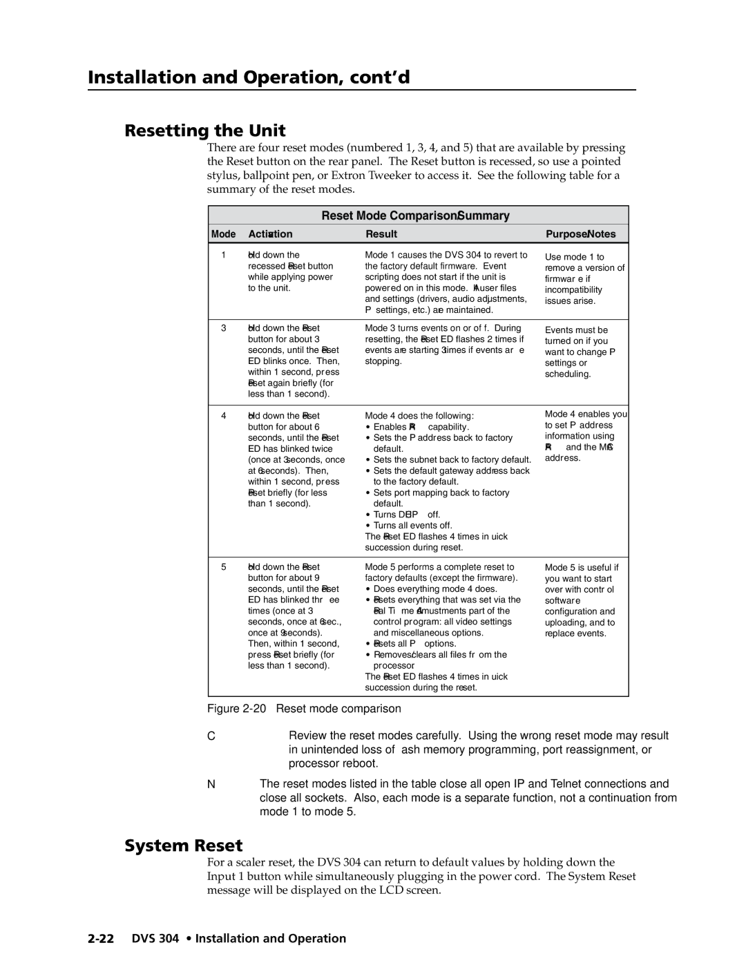
There are four reset modes (numbered 1, 3, 4, and 5) that are available by pressing the Reset button on the rear panel. The Reset button is recessed, so use a pointed stylus, ballpoint pen, or Extron Tweeker to access it. See the following table for a summary of the reset modes.
Reset Mode Comparison/Summary
Mode | Activation | Result | Purpose/Notes |
|
|
|
|
1 | Hold down the | Mode 1 causes the DVS 304 to revert to | Use mode 1 to |
| recessed Reset button | the factory default firmware. Event | remove a version of |
| while applying power | scripting does not start if the unit is | firmware if |
| to the unit. | powered on in this mode. All user files | incompatibility |
|
| and settings (drivers, audio adjustments, | issues arise. |
|
| IP settings, etc.) are maintained. |
|
|
|
|
|
3 | Hold down the Reset | Mode 3 turns events on or off. During | Events must be |
| button for about 3 | resetting, the Reset LED flashes 2 times if | turned on if you |
| seconds, until the Reset | events are starting; 3 times if events are | want to change IP |
| LED blinks once. Then, | stopping. | settings or |
| within 1 second, press |
| scheduling. |
| Reset again briefly (for |
|
|
| less than 1 second). |
|
|
|
|
|
|
4 | Hold down the Reset | Mode 4 does the following: | Mode 4 enables you |
| button for about 6 | • Enables ARP capability. | to set IP address |
| seconds, until the Reset | • Sets the IP address back to factory | information using |
| LED has blinked twice | default. | ARP and the MAC |
| (once at 3 seconds, once | • Sets the subnet back to factory default. | address. |
| at 6 seconds). Then, | • Sets the default gateway address back |
|
| within 1 second, press | to the factory default. |
|
| Reset briefly (for less | • Sets port mapping back to factory |
|
| than 1 second). | default. |
|
|
| • Turns DHCP off. |
|
|
| • Turns all events off. |
|
|
| The Reset LED flashes 4 times in quick |
|
|
| succession during reset. |
|
|
|
|
|
5 | Hold down the Reset | Mode 5 performs a complete reset to | Mode 5 is useful if |
| button for about 9 | factory defaults (except the firmware). | you want to start |
| seconds, until the Reset | • Does everything mode 4 does. | over with control |
| LED has blinked three | • Resets everything that was set via the | software |
| times (once at 3 | Real Time Admustments part of the | configuration and |
| seconds, once at 6 sec., | control program: all video settings | uploading, and to |
| once at 9 seconds). | and miscellaneous options. | replace events. |
| Then, within 1 second, | • Resets all IP options. |
|
| press Reset briefly (for | • Removes/clears all files from the |
|
| less than 1 second). | processor. |
|
|
| The Reset LED flashes 4 times in quick |
|
|
| succession during the reset. |
|
Figure 2-20 — Reset mode comparison
CReview the reset modes carefully. Using the wrong reset mode may result in unintended loss of flash memory programming, port reassignment, or processor reboot.
NThe reset modes listed in the table close all open IP and Telnet connections and close all sockets. Also, each mode is a separate function, not a continuation from mode 1 to mode 5.
System Reset
For a scaler reset, the DVS 304 can return to default values by holding down the Input 1 button while simultaneously plugging in the power cord. The System Reset message will be displayed on the LCD screen.