Programmer’s Guide
RS-232 Link
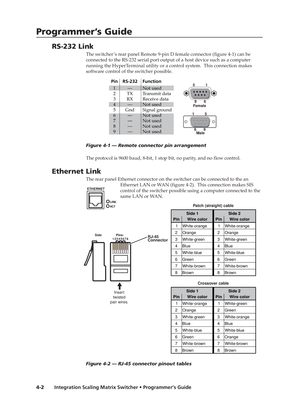
The switcher’s rear panel Remote
Pin | Function | 5 | 1 | ||
1 | — | Not used | |||
|
| ||||
2 | TX | Transmit data |
|
| |
3 | RX | Receive data | 9 | 6 | |
4 | — | Not used | |||
Female | |||||
5 | Gnd | Signal ground | 1 | 5 | |
6 | — | Not used | |||
7 | — | Not used |
|
| |
8 | — | Not used | 6 | 9 | |
9 | — | Not used | |||
Male | |||||
Figure 4-1 — Remote connector pin arrangement
The protocol is 9600 baud,
Ethernet Link
The rear panel Ethernet connector on the switcher can be connected to the an
Ethernet LAN or WAN (figure
ETHERNET control of the switcher possible using a computer connected to the same LAN or WAN.
LINK
ACT
Side Pins:
1 2 3 4 5 6 7 8
Insert
twisted pair wires.
Patch (straight) cable
|
| Side 1 |
| Side 2 | |
| Pin | Wire color | Pin | Wire color | |
| 1 | 1 | |||
|
|
|
|
| |
2 | Orange | 2 | Orange | ||
|
|
|
| ||
3 | 3 | ||||
Connector | |||||
| 4 | Blue | 4 | Blue | |
| 5 | 5 | |||
|
|
|
|
| |
| 6 | Green | 6 | Green | |
|
|
|
|
| |
| 7 | 7 | |||
|
|
|
|
| |
| 8 | Brown | 8 | Brown | |
|
|
|
|
|
Crossover cable
| Side 1 |
| Side 2 |
Pin | Wire color | Pin | Wire color |
1 | 1 | ||
|
|
|
|
2 | Orange | 2 | Green |
|
|
|
|
3 | 3 | ||
4 | Blue | 4 | Blue |
|
|
|
|
5 | 5 | ||
|
|
|
|
6 | Green | 6 | Orange |
|
|
|
|
7 | 7 | ||
8 | Brown | 8 | Brown |
|
|
|
|